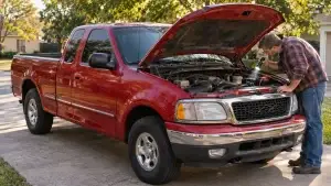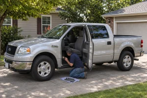

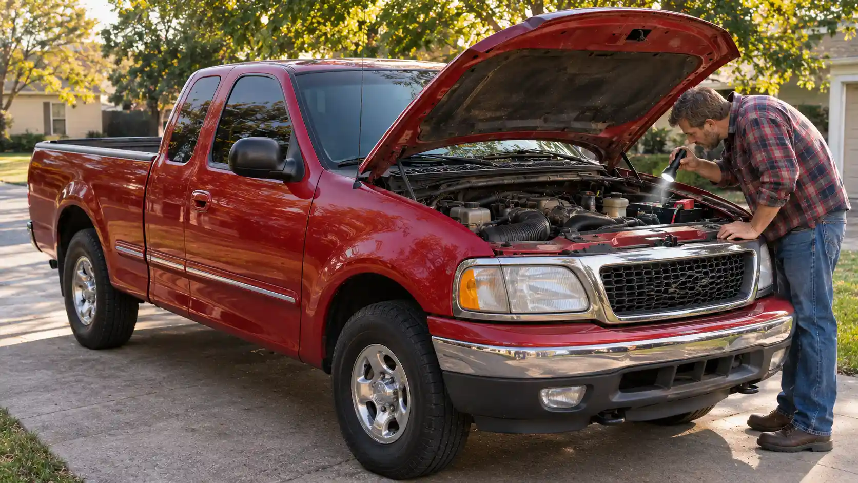
On a 1997–2003 Ford F-150, the cabin fuse panel is below and to the left of the steering wheel, by the brake pedal, behind a cover. The power distribution box is under the hood on the driver’s side. 1997–1998 trucks also have primary battery fuses (megafuses) and a small engine mini-fuse panel under the hood.
That’s the opposite side from every later F-150, which puts the cabin panel on the passenger side. It’s also why so many owners of these trucks can’t find the fuse box.
For other years, see our F-150 fuse box diagram for every year. If you have a 2004 F-150 with the new, redesigned body, you need the 2004–2008 F-150 fuse box diagram instead.
These charts cover every engine in this generation: the 4.2L V6, 4.6L V8 and 5.4L Triton V8. A few rows apply only to the SuperCrew, the supercharged SVT Lightning, the Harley-Davidson edition or bi-fuel trucks, and the tables mark each one.
2004 F-150 Heritage owners: use the 2003 charts
The 2004 F-150 Heritage is the carryover 10th-gen truck, sold alongside the new 2004 model. Its fuse boxes match the 2003 truck, so use the 2002–2003 instrument panel chart and the 2003 power distribution box chart on this page.
Find your year
| Jump to | Covers |
|---|---|
| Cabin panel 1997–1998 | Instrument panel fuses, original layout |
| Cabin panel 1999 | Instrument panel fuses and relays |
| Cabin panel 2000–2001 | Instrument panel fuses and relays |
| Cabin panel 2002–2003 | Instrument panel fuses and relays (also 2004 Heritage) |
| Under-hood 1997–1998 | Power distribution box, megafuses, mini-fuse panel |
| Under-hood 1999 | Power distribution box and relays |
| Under-hood 2000–2001 | Power distribution box, relays and diodes |
| Under-hood 2002 | Power distribution box |
| Under-hood 2003 | Power distribution box, relays and diodes (also 2004 Heritage) |
| Quick reference | The most-searched fuses for every year in one table |
F-150 fuse box location (1997–2003)
The 2003 F150 fuse box location is the same as the 2001 F150 fuse box location and every other year in this generation: the cabin panel on the driver’s side by the brake pedal, and the power distribution box under the hood on the driver’s side. Newer trucks moved the cabin panel to the passenger side (for example, the 2021–2026 F-150 fuse box sits in the passenger footwell), so don’t go looking there on a 10th-gen truck.
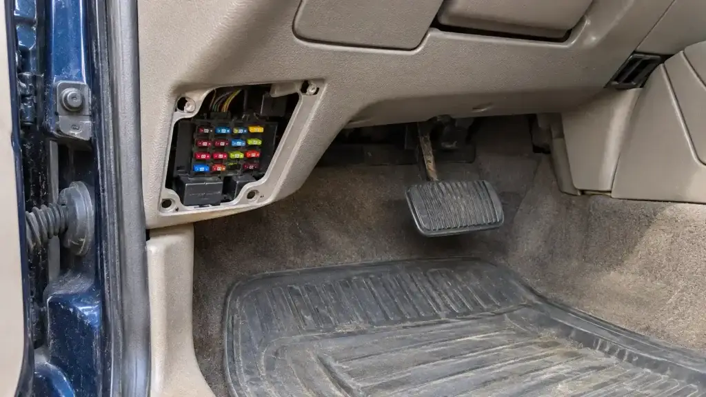
Instrument panel fuse panel (driver’s side, by the brake pedal)
Ford calls this the instrument panel fuse panel. It holds the cigar lighter, radio, wiper, high-beam, brake/turn and OBD port fuses.
- Turn the ignition off.
- Open the driver’s door and look below and to the left of the steering wheel, by the brake pedal.
- Remove the panel cover.
- Unclip the fuse puller from the panel cover; Ford keeps one there.
- Find your fuse using the chart for your year below, and refit the cover when you’re done.
Power distribution box (under the hood, driver’s side)
The power distribution box holds the high-current fuses and most relays: fuel pump, horn, power point, blower motor, power windows, 4×4 and trailer tow.
- Open the hood and find the power distribution box on the driver’s side of the engine compartment.
- Release the lid and lift it off.
- Use the chart for your year: 1997–1998 trucks use a different box (positions 1–29) from 1999–2003 trucks (positions 1–24 and 101–118).
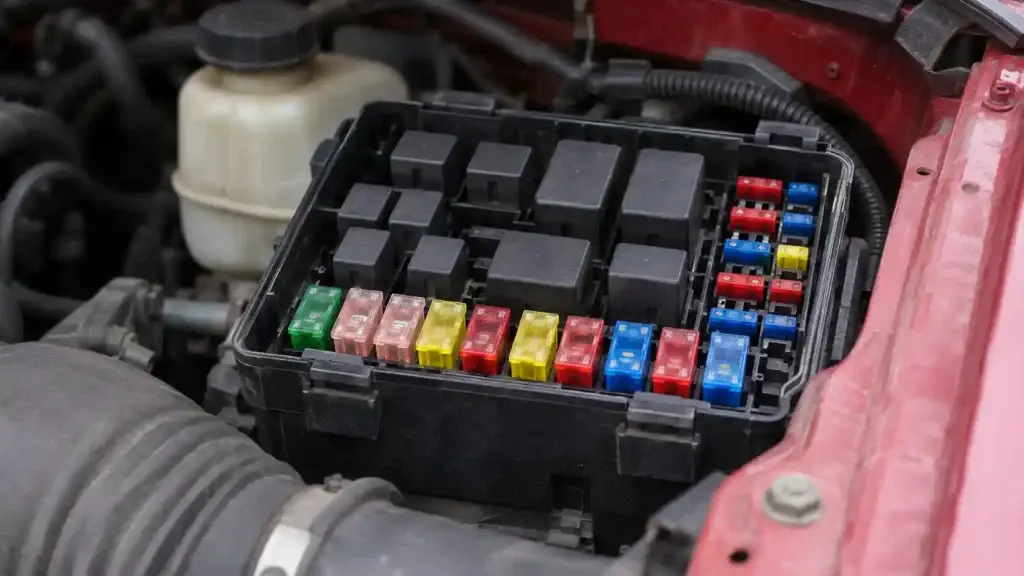
1997–1998 only: megafuses and the engine mini-fuse panel
- Primary battery fuses (megafuses): under the “PRIMARY BATTERY FUSE” cover next to the starter relay. These are the 175A power network box and alternator fuses and a 20A alternator field fuse. Ford recommends a qualified technician service them; don’t replace them yourself.
- Engine mini-fuse panel: behind the power distribution box. It holds a 5A PCM fuse and the 20A trailer tow stop/turn lamp fuse.
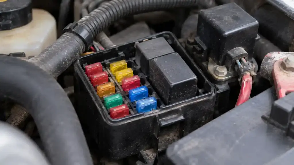
1999–2003 relay boxes
On 1999–2003 trucks there are also small relay boxes behind the left and right sides of the instrument panel. Bi-fuel trucks add a relay module at the left rear of the engine compartment.
Quick reference: most-searched F-150 fuses by year
“PDB” = power distribution box under the hood. “Cabin” = instrument panel fuse panel (left of the steering wheel). 2004 Heritage owners use the 2003 column.
| Circuit | 1997–1998 | 1999 | 2000–2001 | 2002 | 2003 |
|---|---|---|---|---|---|
| Cigar lighter | Cabin 3 (25A) | Cabin 3 (20A) | Cabin 3 (20A) | Cabin 3 (20A) | Cabin 3 (20A) |
| Front power point | PDB 10 (25A) | PDB 1 (25A) | PDB 1 (20A) | PDB 1 (20A) | PDB 1 (20A) |
| Rear power point | — | — | PDB 12 (20A) | PDB 12 (20A) | PDB 12 (20A) |
| Radio / audio | PDB 6 (15A) + cabin 8 (5A) | Cabin 1 (15A) | Cabin 1 (15A) | Cabin 1 (15A) | Cabin 1 (15A) |
| Horn | PDB 5 (20A) | PDB 7 (20A) | PDB 7 (20A) | PDB 7 (20A) | PDB 7 (20A) |
| Fuel pump | PDB 19 (20A) | PDB 10 (20A) | PDB 10 (20A) | PDB 10 (20A) | PDB 10 (20A) |
| Headlamps (low beam) | PDB 8 (30A) + cabin 26 R / 28 L (10A) | Cabin 26 R / 28 L (10A) | Cabin 26 R / 28 L (10A) | Cabin 26 R / 28 L (10A) | Cabin 26 R / 28 L (10A) |
| High beams | Cabin 16 (20A) | Cabin 16 (20A) | Cabin 16 (20A) | Cabin 16 (20A) | Cabin 16 (20A) |
| Brake / turn lamps | Cabin 1 (15A, flasher), 13 (15A) | Cabin 13 (20A) | Cabin 13 (20A) | Cabin 13 (20A) | Cabin 13 (20A) |
| Wipers | Cabin 11 (30A) | Cabin 11 (30A) | Cabin 11 (30A) | Cabin 11 (30A) | Cabin 11 (30A) |
| Blower motor | PDB 23 (40A) | PDB 105 (40A) | PDB 105 (40A) | PDB 105 (40A) | PDB 105 (40A) |
| Power windows | PDB 25 (30A) | PDB 110 (30A) | PDB 601 (30A CB) | PDB 601 (30A CB) | PDB 601 (30A CB) |
| Trailer brake controller | PDB 28 (30A) | PDB 108 (30A) | PDB 108 (30A) | PDB 108 (30A) | PDB 108 (30A) |
| Trailer stop/turn lamps | Mini-fuse 2 (20A) | PDB 19 R / 20 L (10A) | PDB 19 R / 20 L (10A) | PDB 19 R / 20 L (10A) | PDB 19 R / 20 L (10A) |
| 4×4 shift motor | PDB 17 (30A) | PDB 104 (30A) | PDB 104 (30A) | PDB 104 (30A) | PDB 104 (30A) |
| OBD port (data link connector) | Cabin 12 (5A) | Cabin 3 (20A) | Cabin 3 (20A) | Cabin 3 (20A) | Cabin 3 (20A) |
“CB” = circuit breaker.
1997–1998 Ford F-150 fuse box diagram: instrument panel
This is the 1997 Ford F150 fuse box diagram for the cabin panel, and the 1998 truck uses the same chart. The cigar lighter is fuse 3 at 25A (later trucks use 20A), the OBD port has its own 5A fuse (12), and fuse 1 feeds the flasher relay rather than the radio.
Fuse 5 depends on build date: trucks built before 6/24/96 have a transmission range sensor, and later trucks have a digital transmission range sensor.
[custom diagram: 1997–1998 instrument panel fuse panel]
| Fuse | Amps | Circuits protected |
|---|---|---|
| 1 | 15A | Flasher relay |
| 2 | 5A | Instrument cluster |
| 3 | 25A | Cigar lighter |
| 4 | 5A | Park lamp relay, headlamp relay, autolamp module, remote anti-theft (RAP) module, power mirror switch |
| 5 | 15A | Transmission range sensor (built before 6/24/96) or digital transmission range sensor (built after), back-up lamp switch (manual), daytime running lamps module, speed control, heater/A-C control, blend door actuator |
| 6 | 5A | Shift lock actuator, generic electronic module (GEM), rear air suspension module |
| 8 | 5A | Radio, main light switch, remote anti-theft (RAP) module |
| 11 | 30A | Washer pump relay, wiper run/park relay, wiper hi/lo relay, windshield wiper motor |
| 12 | 5A | Data link connector (OBD port) |
| 13 | 15A | Rear anti-lock brake (RABS) module, brake on/off switch, brake pressure switch |
| 14 | 15A | Battery saver relay, interior lamp relay |
| 15 | 5A | Generic electronic module (GEM) |
| 16 | 20A | Instrument cluster (without DRL), daytime running lamps module, high-beam headlamps |
| 18 | 5A | Park lamp relay, trailer electronic brake controller, main light switch, trailer tow run relay, front park/turn lamps, license lamps, stop/park/turn lamps, tail/side marker lamps |
| 19 | 10A | Instrument cluster, air bag diagnostic monitor |
| 20 | 5A | PCM, generic electronic module / central timer module |
| 21 | 15A | Clutch pedal position switch (without RAP), starter interrupt relay (with RAP) |
| 22 | 10A | Air bag diagnostic monitor, passenger airbag deactivation module |
| 23 | 10A | Trailer tow battery charge relay, 4×4 and 4×2 hub solenoids, flasher relay, shift-on-the-fly relay |
| 24 | 10A | Blower relay |
| 25 | 5A | 4-wheel anti-lock brake (4WABS) module and relay |
| 26 | 10A | Daytime running lamps module, right headlamp |
| 27 | 5A | Main light switch, fog lamp relay |
| 28 | 10A | Left headlamp |
| 29 | 5A | Autolamp module, instrument cluster, transmission control switch, brake warning resistor/diode (with RABS) |
| 30 | 30A | Radio noise capacitor, ignition coil, PCM power diode |
1999 Ford F-150 fuse box diagram: instrument panel
The 1999 Ford F150 fuse box diagram for the cabin keeps the same panel positions as 1997–1998, but many circuits changed. Fuse 1 is now the 15A audio fuse, the cigar lighter (fuse 3) drops to 20A and also feeds the OBD-II connector, and fuse 13 (20A) handles the stop lamps and turn/hazard flasher.
[custom diagram: 1999 instrument panel fuse panel]
| Fuse | Amps | Circuits protected |
|---|---|---|
| 1 | 15A | Audio |
| 2 | 5A | PCM, instrument cluster |
| 3 | 20A | Cigar lighter, OBD-II scan tool connector |
| 4 | 15A | Autolamp module, remote entry module, mirrors |
| 5 | 15A | A/C clutch relay, speed control module, reverse lamp, climate mode switch, daytime running lamp relay |
| 6 | 5A | Instrument cluster, brake shift interlock solenoid, rear air suspension module, GEM module |
| 8 | 5A | Radio, remote entry module, GEM module |
| 11 | 30A | Front washer pump relay, wiper run/park relay, wiper hi/lo relay, windshield wiper motor |
| 13 | 20A | Stop lamp switch (lamps), turn/hazard flasher, speed control module |
| 14 | 15A | Battery saver relay, interior lamp relay, accessory delay relay (power windows) |
| 15 | 5A | Stop lamp switch (speed control, brake shift interlock, ABS, PCM inputs), GEM module, RABS test connector |
| 16 | 20A | High-beam headlamps, cluster high-beam indicator |
| 18 | 5A | Instrument illumination (dimmer switch power) |
| 20 | 5A | Audio, GEM module, PCM |
| 21 | 15A | Starter relay, clutch switch, fuse 20 |
| 22 | 10A | Air bag module, passenger airbag deactivation module |
| 23 | 10A | Trailer tow battery charge relay, turn/hazard flasher, 4×4 solenoids, 4×4 relays |
| 24 | 10A | Climate mode switch (blower relay) |
| 25 | 5A | 4-wheel anti-lock brake (4WABS) module |
| 26 | 10A | Right low-beam headlamp |
| 27 | 5A | Fog lamp relay and fog lamp indicator |
| 28 | 10A | Left low-beam headlamp |
| 29 | 5A | Autolamp module, transmission overdrive control switch |
| 30 | 30A | Passive anti-theft transceiver, instrument cluster, ignition coils, PCM relay |
Relays in this panel: 1 interior lamp relay; 2 battery saver relay; 4 one-touch-down window relay; 5 accessory delay relay.
2000–2001 Ford F-150 fuse box diagram: instrument panel
This 2001 Ford F150 fuse diagram for the cabin also covers the 2000 truck. Compared with 1999, fuse 4 now feeds the exterior mirror switch and mirror turn signal relays, fuse 8 adds the SuperCrew’s in-vehicle entertainment system, fuse 23 picks up the overhead console, 4WABS module, auto-dimming mirror and heated seats, and fuse 25 is no longer listed.
[custom diagram: 2000–2001 instrument panel fuse panel]
| Fuse | Amps | Circuits protected |
|---|---|---|
| 1 | 15A | Audio |
| 2 | 5A | PCM, instrument cluster |
| 3 | 20A | Cigar lighter, data link connector (OBD port) |
| 4 | 5A | Exterior mirror switch, mirror turn signal relays |
| 5 | 15A | Speed control module, reverse lamp, climate mode switch, daytime running lamp relay, digital transmission range sensor |
| 6 | 5A | Instrument cluster, brake shift interlock solenoid, GEM module |
| 8 | 5A | Radio, remote entry module, GEM module, in-vehicle entertainment system (SuperCrew only) |
| 11 | 30A | Front washer pump relay, wiper run/park relay, wiper hi/lo relay, windshield wiper motor |
| 13 | 20A | Stop lamp switch (lamps), turn/hazard flasher |
| 14 | 15A | Battery saver relay, interior lamp relay |
| 15 | 5A | Stop lamp switch (speed control, brake shift interlock), GEM module, RABS module |
| 16 | 20A | High-beam headlamps, cluster high-beam indicator |
| 18 | 5A | Instrument illumination (dimmer switch power) |
| 20 | 5A | Audio, GEM module, PCM, transmission range sensor |
| 21 | 15A | Digital transmission range sensor, clutch switch, starter relay, I/P fuse 20 |
| 22 | 10A | Air bag module, passenger airbag deactivation module |
| 23 | 10A | Trailer tow battery charge relay, turn/hazard flasher, 4×4 solenoids, 4×4 relays, overhead console, 4WABS module, auto-dimming mirror, heated seats |
| 24 | 10A | Function selector switch assembly |
| 26 | 10A | Right low-beam headlamp |
| 27 | 5A | Fog lamp relay and fog lamp indicator, main light switch |
| 28 | 10A | Left low-beam headlamp |
| 29 | 5A | Autolamp module, transmission overdrive control switch, central security module, Belt-Minder |
| 30 | 30A | Passive anti-theft transceiver, instrument cluster, ignition coils, PCM relay, coil-on-plugs, radio noise capacitor, diode |
Relays in this panel: 1 interior lamp relay; 2 battery saver relay; 4 one-touch-down window relay; 5 accessory delay relay.
2002–2003 Ford F-150 fuse box diagram: instrument panel (and 2004 Heritage)
This 2003 F150 fuse panel diagram also covers the 2002 Ford F150 fuse box diagram for the cabin, and the 2004 F-150 Heritage. It’s close to the 2000–2001 chart, with a few wording changes: fuse 1 lists the radio and CD changer, and fuse 24 notes the blower motor relay and automatic climate control.
One row is marked ⚠️ because published charts disagree on it.
[custom diagram: 2002–2003 instrument panel fuse panel]
| Fuse | Amps | Circuits protected |
|---|---|---|
| 1 | 15A | Audio (radio, CD changer) |
| 2 | 5A | PCM, instrument cluster |
| 3 | 20A | Cigar lighter, data link connector (OBD port) |
| 4 | 5A | Power mirror switch, mirror turn signal relays |
| 5 | 15A | Speed control module, reverse lamp, climate mode switch, daytime running lamps relay, digital transmission range sensor |
| 6 | 5A | Instrument cluster, brake shift interlock solenoid, GEM module |
| 8 | 5A | Radio, remote entry module, GEM module, in-vehicle entertainment system (SuperCrew only) |
| 11 | 30A | Front washer pump relay, wiper run/park relay, wiper hi/lo relay, windshield wiper motor |
| 13 | 20A | Stop lamp switch (lamps), turn/hazard flasher |
| 14 | 15A | Battery saver relay, interior lamp relay |
| 15 | 5A | Stop lamp switch (speed control, brake shift interlock), GEM module, rear anti-lock brake module |
| 16 | 20A | High-beam headlamps, cluster high-beam indicator |
| 18 | 5A | Instrument illumination (dimmer switch power) |
| 20 | 5A | Audio, GEM module, PCM, transmission range sensor |
| 21 | 15A | Digital transmission range sensor, clutch switch, starter relay, I/P fuse 20 |
| 22 | 10A | Air bag module, passenger airbag deactivation module |
| 23 | 10A | Trailer tow battery charge relay, turn/hazard flasher, 4×4 solenoids and relays, overhead console, 4WABS module, auto-dimming mirror, heated seats |
| 24 | 10A | Function selector switch assembly (blower motor relay, automatic climate control) |
| 25 ⚠️ | 10A | Heated mirrors (listed on one 2003 chart; another chart shows this position as not used on 2002–2003. Confirm on your fuse panel cover) |
| 26 | 10A | Right low-beam headlamp |
| 27 | 5A | Fog lamp relay and fog lamp indicator, main light switch |
| 28 | 10A | Left low-beam headlamp |
| 29 | 5A | Autolamp module, transmission overdrive control switch, central security module, Belt-Minder |
| 30 | 30A | Passive anti-theft transceiver, instrument cluster, ignition coils, PCM relay, coil-on-plugs, radio noise capacitor |
Relays in this panel: 1 interior lamp relay; 2 battery saver relay; 4 one-touch-down window relay; 5 accessory delay relay.
1997–1998 Ford F-150 fuse box diagram: under the hood
The 1998 Ford F150 fuse box diagram for the engine compartment (and the 1997) uses a power distribution box numbered 1–29, plus two extra fuse locations no later truck has: the megafuses and the engine mini-fuse panel. Here the fuel pump is position 19, the horn is 5 and the power point is 10.
[custom diagram: 1997–1998 power distribution box]
1997–1998 power distribution box (driver’s side)
| Position | Amps | Circuits protected |
|---|---|---|
| 1 | 20A | Trailer tow back-up and tail lamps |
| 2 | 10A | Air bag diagnostic monitor |
| 3 | 15A | Power locks (or not used) |
| 4 | 15A | Air suspension (or not used) |
| 5 | 20A | Horn |
| 6 | 15A | Audio system |
| 7 | 15A | Parking and tail lamps |
| 8 | 30A | Headlamps |
| 9 | 15A | Daytime running lamps and fog lamps |
| 10 | 25A | Auxiliary power point |
| 14 | 60A / 20A | 4-wheel anti-lock brakes / rear anti-lock brakes, ignition switch |
| 15 | 50A | Air suspension compressor (or not used) |
| 16 | 40A | Trailer tow battery charge and stop/turn lamps |
| 17 | 30A | 4WD transfer case shift motor and clutch |
| 18 | 30A | Driver power seat |
| 19 | 20A | Fuel pump |
| 20 | 50A | Instrument panel fuse panel – ignition switch feed |
| 21 | 50A | Instrument panel fuse panel – ignition switch feed |
| 22 | 50A | Instrument panel fuse panel – battery feed |
| 23 | 40A | Blower motor |
| 24 | 30A | PCM power |
| 25 | 30A | Power windows |
| 26 | 20A | Power locks (or not used) |
| 28 | 30A | Trailer tow electronic brake |
Relays and diodes: R1 wiper hi/lo speed; R2 wiper run/park; R3 washer pump; R4 fuel pump; R5 horn; R6 PCM power; D1 rear ABS diode; D2 PCM diode.
Primary battery fuses (megafuses), 1997–1998
Under the “PRIMARY BATTERY FUSE” cover next to the starter relay. Ford recommends a qualified technician service these.
| Megafuse | Amps | Circuit |
|---|---|---|
| 1 | 175A | Power network box |
| 2 | 175A | Alternator |
| 3 | 20A | Alternator field |
Engine mini-fuse panel, 1997–1998
Behind the power distribution box.
| Mini-fuse | Amps | Circuit |
|---|---|---|
| 1 | 5A | PCM |
| 2 | 20A | Trailer tow stop/turn lamps |
1999 Ford F-150 fuse box diagram: under the hood
For 1999 Ford introduced the newer power distribution box, with positions 1–24 and 101–118 used through 2003. The power point moves to fuse 1 (25A), the horn to 7 and the fuel pump to 10. The megafuses and mini-fuse panel are gone.
[custom diagram: 1999 power distribution box]
| Fuse | Amps | Circuits protected |
|---|---|---|
| 1 | 25A | Power point |
| 2 | 30A | PCM |
| 3 | 30A | Headlamps / autolamps |
| 4 | 15A | Air suspension |
| 5 | 20A | Trailer tow back-up / park lamps |
| 6 | 15A | Park lamps / autolamps |
| 7 | 20A | Horn |
| 8 | 15A | Power door locks |
| 9 | 15A | Daytime running lamps, fog lamps |
| 10 | 20A | Fuel pump |
| 11 | 20A | Alternator field |
| 18 | 15A | PCM, fuel injectors, fuel pump, mass air flow sensor |
| 19 | 10A | Trailer tow stop and right turn lamp |
| 20 | 10A | Trailer tow stop and left turn lamp |
| 23 | 15A | PCM, oxygen (HEGO) sensor, canister vent |
| 24 | 15A | PCM, automatic transmission, CMS sensor |
| 101 | 30A | Trailer tow battery charge |
| 102 | 50A / 20A | 4-wheel anti-lock brake module / rear anti-lock brake module |
| 103 | 50A | Junction block battery feed |
| 104 | 30A | 4×4 shift motor and clutch |
| 105 | 40A | Front blower motor |
| 108 | 30A | Trailer tow electric brake |
| 109 | 50A | Air suspension compressor |
| 110 | 30A | Power windows |
| 111 | 50A | Ignition switch battery feed (start and run circuits) |
| 112 | 30A | Driver power seat |
| 113 | 50A | Ignition switch battery feed (run and accessory circuits) |
Relays: 201 trailer tow park lamp; 202 front wiper run/park; 203 trailer tow back-up lamp; 204 A/C clutch; 205 horn; 206 fog lamp; 207 front washer pump; 209 front wiper hi/lo; 301 fuel pump; 302 trailer tow battery charge; 303 rear air suspension; 304 PCM.
2000–2001 Ford F-150 fuse box diagram: under the hood
This is the 2000 and 2001 Ford F150 fuse box diagram for the engine compartment. The power point (fuse 1) drops to 20A, a rear auxiliary power point appears on fuse 12, and the power windows move to a 30A circuit breaker (601). Fuse 106 and relay 208 are for the SVT Lightning’s intercooler pump, and a few rows differ on the SuperCrew.
[custom diagram: 2000–2001 power distribution box]
| Fuse | Amps | Circuits protected |
|---|---|---|
| 1 | 20A | Power point |
| 2 | 30A | PCM |
| 3 | 30A | Headlamps / autolamps |
| 5 | 20A | Trailer tow back-up / park lamps |
| 6 | 15A | Park lamps / autolamps, feed to cabin fuse 18 |
| 7 | 20A | Horn |
| 8 | 15A | Power door locks, central security module, lock relays (except SuperCrew; not used on SuperCrew) |
| 9 | 15A | Daytime running lamps, fog lamps |
| 10 | 20A | Fuel pump |
| 11 | 20A | Alternator field |
| 12 | 20A | Rear auxiliary power point |
| 13 | 15A | A/C clutch |
| 18 | 15A | PCM, fuel injectors, fuel pump relay, idle air control, mass air flow sensor |
| 19 | 10A | Trailer tow stop and right turn lamp |
| 20 | 10A | Trailer tow stop and left turn lamp |
| 23 | 15A | Oxygen (HEGO) sensor, canister vent, automatic transmission, CMS sensor |
| 101 | 30A | Trailer tow battery charge |
| 102 | 50A / 20A | 4-wheel anti-lock brake module, or rear anti-lock brake module and ignition switch (except SuperCrew) |
| 103 | 50A | Junction block battery feed |
| 104 | 30A | 4×4 shift motor and clutch |
| 105 | 40A | Front blower motor |
| 106 | 20A | Intercooler pump (SVT Lightning only; not used on others) |
| 108 | 30A | Trailer tow electric brake |
| 110 | 30A | Accessory delay relay (except SuperCrew; not used on SuperCrew) |
| 111 | 40A | Ignition switch battery feed (start and run circuits) |
| 112 | 30A | Driver power seat, adjustable pedals |
| 113 | 40A | Ignition switch battery feed (run and accessory circuits) |
| 115 | 20A | Power door locks |
| 118 | 30A | Heated seats (except SuperCrew; not used on SuperCrew) |
| 601 | 30A circuit breaker | Power windows, moonroof |
Relays and diodes: 201 trailer tow park lamp; 202 front wiper run/park; 203 trailer tow back-up lamp; 204 A/C clutch; 205 horn; 206 fog lamp; 207 front washer pump; 208 intercooler pump (SVT Lightning only); 209 front wiper hi/lo; 301 fuel pump; 302 trailer tow battery charge; 304 PCM; 501 PCM diode; 502 A/C compressor diode.
2002 Ford F-150 fuse box diagram: under the hood
The 2002 Ford F150 fuse box diagram for the engine bay keeps the 2000–2001 numbering, but the 2002 owner’s-manual chart describes many fuses by the relay or module they feed. For example, fuse 10 is listed as the fuel pump relay and fuse 7 as the horn relay. New for 2002: fuse 15 (10A) for the running board lamps.
[custom diagram: 2002 power distribution box]
| Fuse | Amps | Circuits protected |
|---|---|---|
| 1 | 20A | Power point |
| 2 | 30A | PCM power relay |
| 3 | 30A | Main light switch, headlamp relay, multifunction switch |
| 5 | 20A | Trailer tow park lamp relay, trailer tow reversing lamp relay |
| 6 | 15A | Main light switch, park lamp relay |
| 7 | 20A | Horn relay |
| 8 | 15A | Door lock switches, central security module |
| 9 | 15A | Daytime running lamps resistor, fog lamp relay |
| 10 | 20A | Fuel pump relay |
| 11 | 20A | Alternator (generator) |
| 12 | 20A | Rear power point |
| 13 | 15A | A/C clutch relay |
| 15 | 10A | Running board lamps |
| 18 | 15A | Mass air flow sensor, PCM, fuel injectors 1–8, idle air control valve, fuel pump relay, fuel pump cutoff relay |
| 19 | 10A | Trailer tow connector (right stop/turn) |
| 20 | 10A | Trailer tow connector (left stop/turn) |
| 23 | 15A | EVAP canister vent and purge valves, oxygen sensors, A/C clutch relay, automatic transmission module, camshaft position sensor, intake manifold runner control, bi-fuel power relay |
| 101 | 30A | Trailer tow battery charge relay |
| 102 | 50A | ABS control module |
| 103 | 50A | Central junction box |
| 104 | 30A | Transfer case relay module, transfer case electric clutch relay, shift-on-the-fly relay |
| 105 | 40A | Blower motor relay |
| 106 | 20A | Charge air cooler pump relay (SVT Lightning) |
| 108 | 30A | Trailer tow connector (electric brakes) |
| 110 | 30A | Accessory delay relay |
| 111 | 40A | Ignition switch |
| 112 | 30A | Adjustable pedal switch, driver power seat switch |
| 113 | 40A | Ignition switch |
| 115 | 20A | Door lock switches, central security module |
| 118 | 30A | Driver and passenger heated seat modules |
| 601 | 30A circuit breaker | Accessory delay relay (power windows) |
The 2002 chart we used doesn’t list relay positions. The 2000–2001 and 2003 relay lists on this page may help, but confirm on your fuse box cover before swapping a relay.
2003 Ford F-150 fuse box diagram: under the hood (and 2004 Heritage)
This is the 2003 Ford F150 fuse box diagram for the power distribution box, and it also covers the 2004 F-150 Heritage. 2003 adds several version-specific rows: a console power point for the Harley-Davidson edition (fuse 4), bi-fuel injector circuits (fuse 16), a heated rear window fuse (116), an audiophile radio fuse for the SuperCrew (117), and fuel pump and inertia switch relays on the supercharged SVT Lightning (305 and 306).
[custom diagram: 2003 power distribution box]
| Fuse | Amps | Circuits protected |
|---|---|---|
| 1 | 20A | Power point |
| 2 | 30A | PCM |
| 3 | 30A | Main light switch, headlamp relay, multifunction switch |
| 4 | 20A | Console power point (Harley-Davidson edition) |
| 5 | 20A | Trailer tow back-up / park lamps |
| 6 | 15A | Main light switch, park lamp relay |
| 7 | 20A | Horn |
| 8 | 15A | Power door locks, central security module, lock relays (not used on SuperCrew) |
| 9 | 15A | Daytime running lamps, fog lamps |
| 10 | 20A | Fuel pump |
| 11 | 20A | Alternator field |
| 12 | 20A | Rear auxiliary power point (SuperCrew) |
| 13 | 15A | A/C clutch |
| 15 | 10A | Running board lamps |
| 16 | 15A | Bi-fuel injector module, fuel selector switch, alternative fuel injectors (bi-fuel trucks only) |
| 18 | 15A | PCM, fuel injectors, fuel pump relay, mass air flow sensor |
| 19 | 10A | Trailer / camper adapter (right stop/turn lamp) |
| 20 | 10A | Trailer / camper adapter (left stop/turn lamp) |
| 23 | 15A | Oxygen (HEGO) sensor, automatic transmission |
| 101 | 30A | Trailer tow battery charge |
| 102 | 50A / 20A | 4-wheel / rear anti-lock brake module, ignition switch |
| 103 | 50A | Central junction box |
| 104 | 30A | 4×4 shift motor and clutch |
| 105 | 40A | Front blower motor |
| 106 | 20A | Intercooler pump (supercharged SVT Lightning only) |
| 108 | 30A | Trailer tow electric brake |
| 110 | 30A | Accessory delay relay (not used on SuperCrew) |
| 111 | 40A | Ignition switch battery feed (start and run circuits) |
| 112 | 30A | Driver power seat, adjustable pedal switch |
| 113 | 40A | Ignition switch battery feed (run and accessory circuits) |
| 115 | 20A | Power door locks (SuperCrew only) |
| 116 | 40A | Heated rear window |
| 117 | 40A | Audiophile radio (SuperCrew only) |
| 118 | 30A | Heated seats |
| 601 | 30A circuit breaker | Power windows, moonroof (SuperCrew) |
Relays and diodes: 201 trailer tow park lamp; 202 front wiper run/park; 203 trailer tow back-up lamp; 204 A/C clutch; 205 horn; 206 fog lamp; 207 front washer pump; 208 intercooler pump (supercharged only); 209 front wiper hi/lo; 301 fuel pump; 302 trailer tow battery charge; 303 heated rear window (SuperCrew); 304 PCM; 305 fuel pump hi/lo (supercharged only); 306 inertia switch relay (supercharged only); 501 PCM diode; 502 A/C compressor diode.
Why 1997–1998 trucks are different
The 1997 and 1998 F-150 use a different under-hood box (positions 1–29) from the 1999–2003 trucks (positions 1–24 and 101–118), plus megafuses and a mini-fuse panel. The cabin panel keeps the same positions, but several circuits changed for 1999.
| Circuit | 1997–1998 | 1999–2003 |
|---|---|---|
| Fuel pump | PDB 19 (20A) | PDB 10 (20A) |
| Horn | PDB 5 (20A) | PDB 7 (20A) |
| Blower motor | PDB 23 (40A) | PDB 105 (40A) |
| Radio / audio | PDB 6 (15A) + cabin 8 (5A) | Cabin 1 (15A) |
The radio is the classic mix-up. On a 1997–1998 truck, cabin fuse 1 is the flasher relay; on 1999–2003 it’s the audio fuse. Use a 2001 chart on a 1998 and you’ll pull the turn-signal fuse looking for the radio.
The cigar lighter stays on cabin fuse 3 for every year, but it’s 25A on 1997–1998 and 20A from 1999. Always match the rating on the chart for your year.
How to check and replace a blown fuse
A blown fuse takes about five minutes to find and swap, as long as you replace it with the exact same amp rating.
What you need: the fuse puller clipped to the cabin panel cover (or needle-nose pliers), a 12V test light or multimeter, a flashlight, and spare fuses in the ratings from your year’s chart.
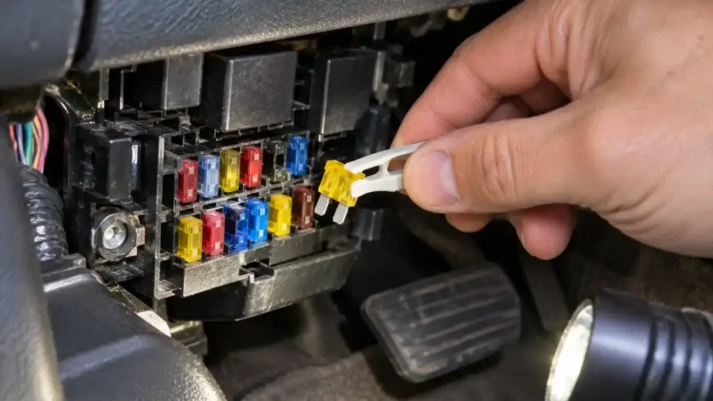
- Find the right fuse. Check the quick reference first, then your year’s full chart. Note which box it’s in (cabin or under-hood), the number and the amp rating.
- Test it in place (fastest). With the key in RUN, clip a test light to bare metal and touch the two small test points on top of the fuse. Light on both sides = good. Light on one side only = blown. A multimeter set to DC volts does the same: about 12 volts on both sides means the fuse is fine.
- Switch off and pull it. Turn the ignition off, then pull the fuse straight out with the puller.
- Look at it. A blown blade fuse has a broken metal strip inside the plastic. A multimeter on continuity confirms it if you can’t tell.
- Fit an identical fuse. Same type, same amp rating, pushed fully into the slot. Where a chart lists two ratings (for example 50A / 20A for 4-wheel vs rear anti-lock brakes), use the one that matches your truck.
- Refit the cover and test. Turn the key on and check the circuit works.
Never fit a higher-rated fuse. The fuse is sized for the wire behind it. A bigger fuse lets the wire overheat instead of the fuse blowing, which is how harness damage and fires start.
Leave the megafuses alone. On 1997–1998 trucks, Ford recommends a qualified technician service the primary battery fuses under the “PRIMARY BATTERY FUSE” cover. They carry battery and alternator current, so don’t replace them yourself.
If the new fuse blows straight away, stop swapping fuses. Something on that circuit is shorted, often a pinched wire, a failed motor or a faulty accessory in a power point. Tracing a short properly needs the full wiring diagrams, which are in the 1997–2003 Ford F-150 workshop manual, not the owner’s manual.
Common 10th-gen F-150 fuse problems (and the exact fuse)
These are the fuse problems 1997–2003 owners search for most. “PDB” means the under-hood box; “cabin” means the panel by the brake pedal. 2004 Heritage owners use the 2003 numbers.
Cigar lighter or power point dead
- Cigar lighter: cabin 3 on every year (25A on 1997–1998, 20A from 1999). On 1999–2003 the same fuse also feeds the OBD port, so if your scan tool won’t power up either, this is the fuse.
- Front power point: PDB 10 (25A) on 1997–1998, PDB 1 (25A) on 1999, PDB 1 (20A) on 2000–2003.
- Rear power point (2000–2003): PDB 12 (20A). On 2003 Harley-Davidson editions, the console power point is PDB 4 (20A).
Radio out
Cabin 1 (15A) on 1999–2003. On 1997–1998 it’s PDB 6 (15A) plus cabin 8 (5A). Don’t pull cabin 1 on a 1997–1998 looking for the radio; that’s the flasher relay.
Horn not working
PDB 5 (20A) on 1997–1998; PDB 7 (20A) on 1999–2003. The horn relay is R5 on 1997–1998 and 205 on 1999–2003.
No start or fuel pump not running
- Cranks but won’t start: fuel pump PDB 19 (20A) on 1997–1998, PDB 10 (20A) on 1999–2003. The fuel pump relay is R4 on 1997–1998 and 301 on 1999–2003. Also check the PCM fuse: PDB 24 (30A) on 1997–1998, PDB 2 (30A) on 1999–2003.
- No crank at all: check cabin 21 (15A), which feeds the starter relay and clutch switch on 1999–2003, and the starter interrupt relay on 1997–1998 trucks with remote anti-theft.
- Key not recognized (1999–2003): cabin 30 (30A) feeds the passive anti-theft transceiver.
If the fuses and relays check out, the fault is elsewhere. For what each model year is known for, see our guide to the best F-150 years.
Headlights or high beams out
- Low beams: cabin 26 (right) and 28 (left), 10A each, on every year. 1997–1998 trucks also have PDB 8 (30A) feeding the headlamps.
- High beams: cabin 16 (20A) on every year.
If both low beams are out at once, a shared feed is more likely than two blown fuses: check PDB 8 on 1997–1998 or PDB 3 (30A) on 1999–2003.
Wipers dead
Cabin 11 (30A) on every year. It also feeds the washer pump and wiper relays.
Trailer lights or trailer brake not working
| Circuit | 1997–1998 | 1999–2003 |
|---|---|---|
| Trailer brake controller | PDB 28 (30A) | PDB 108 (30A) |
| Trailer stop/turn lamps | Mini-fuse 2 (20A) | PDB 19 right / 20 left (10A) |
| Trailer back-up / park lamps | PDB 1 (20A) | PDB 5 (20A) |
| Trailer battery charge | PDB 16 (40A) | PDB 101 (30A) |
4×4 not engaging
4×4 shift motor: PDB 17 (30A) on 1997–1998, PDB 104 (30A) on 1999–2003. The 4×4 solenoids and relays are also fed by cabin 23 (10A) on every year. If these are good, the fault is in the 4×4 hardware itself rather than a fuse.
Before chasing any electrical fault, run your VIN through the NHTSA recall lookup to see whether an open recall covers it.
FAQs
Where is the fuse box on a 2003 Ford F-150?
A 2003 F-150 has two: the instrument panel fuse panel below and to the left of the steering wheel, by the brake pedal, behind a cover, and the power distribution box under the hood on the driver’s side. There are also small relay boxes behind the left and right sides of the instrument panel.
Where is the fuse box on a 1997 Ford F-150?
The cabin fuse panel is in the same place as later 10th-gen trucks: below and to the left of the steering wheel, by the brake pedal. Under the hood there are three locations: the power distribution box on the driver’s side, the primary battery fuses (megafuses) under the “PRIMARY BATTERY FUSE” cover next to the starter relay, and an engine mini-fuse panel behind the power distribution box.
Which fuse is the cigarette lighter on a 1997–2003 F-150?
Cabin fuse 3 on every year: 25A on 1997–1998 and 20A from 1999 to 2003. On 1999–2003 trucks it also powers the OBD port.
Which fuse is the fuel pump on a 2001 F-150?
Under-hood fuse 10 (20A), with the fuel pump relay in position 301. On 1997–1998 trucks it’s fuse 19 (20A).
Why doesn’t my 1998 F-150 match a 2001 fuse diagram?
Ford changed the under-hood power distribution box for 1999, from positions 1–29 to positions 1–24 and 101–118, and dropped the megafuses and mini-fuse panel. The cabin panel kept its positions but many circuits changed. For example, the fuel pump moved from fuse 19 to 10, the horn from 5 to 7, and cabin fuse 1 changed from the flasher relay to the radio.
Which fuse diagram does a 2004 F-150 Heritage use?
The 2004 F-150 Heritage is the carryover 10th-gen truck, so it uses the 2002–2003 instrument panel chart and the 2003 power distribution box chart on this page. The redesigned 2004 F-150 uses the 2004–2008 F-150 fuse box diagram instead. You can confirm either in the owner’s manual on Ford’s owner manual site.