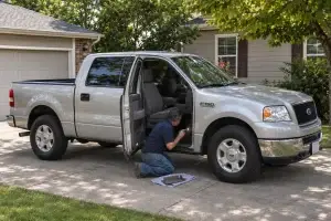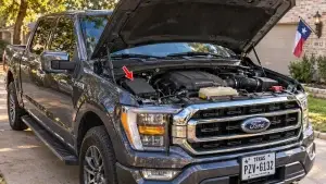

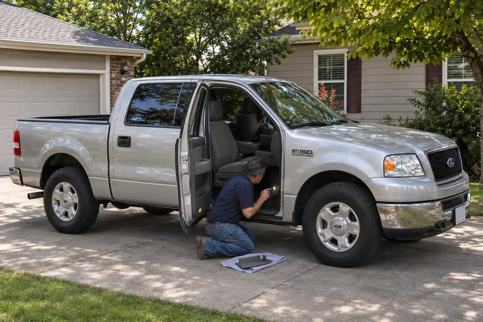
A 2009–2014 Ford F-150 has two fuse boxes: the passenger compartment fuse panel under the passenger side of the dashboard, and the power distribution box under the hood. SVT Raptors add a third, small auxiliary relay box in the left rear corner of the engine bay. The key thing to know: Ford completely renumbered the cabin panel for 2011, so a 2009–2010 chart won’t match a 2011–2014 truck, and the reverse.
The cabin panel is not to the left of the steering wheel, whatever some image results say. That was the 1997–2003 truck. On the 12th generation it sits under the right side of the instrument panel, behind a trim panel.
The under-hood power distribution box keeps the same numbering across all six years, but some circuits changed, so it gets four tables below. For other generations, see our F-150 fuse box diagram for every year, or go back one generation to the 2004–2008 F-150 fuse box diagram.
From 2011 the engine lineup changed to the 3.7L V6, 5.0L V8, 3.5L EcoBoost and 6.2L V8, and a handful of under-hood fuses change rating by engine. The tables mark each one.
Find your year
| Jump to | Covers |
|---|---|
| Cabin fuse panel 2009–2010 | Passenger side under the dash, old numbering |
| Cabin fuse panel 2011–2014 | Passenger side under the dash, new numbering |
| Under-hood box 2009 | Relays and fuses |
| Under-hood box 2010 | Adds electric fan and upfitter circuits |
| Under-hood box 2011–2012 | Adds 110V outlet, EcoBoost PCM and vacuum pump circuits |
| Under-hood box 2013–2014 | Adds HID headlamp fuses; fuse 22 relabeled |
| SVT Raptor relay box | Upfitter / auxiliary switch relays |
| Quick reference | The most-searched fuses for all six years in one table |
F-150 fuse box location (2009–2014)
The 2011 F150 fuse box location is the same as the 2010 F150 fuse box location and every other year in this generation: one panel inside on the passenger side, one box under the hood.
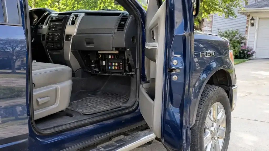
Passenger compartment fuse panel (passenger side)
This panel holds the smaller fuses for lighting, the radio, the horn, the OBD port and most body electronics. You’ll also see it called the smart junction box (SJB); on 2009–2010 trucks, fuse 5 powers the SJB’s microprocessor.
- Turn the ignition off.
- Open the passenger door and look under the right-hand side of the instrument panel.
- Remove the trim panel: pull it toward you, then swing it out away from the side.
- Remove the fuse cover: press in the tabs on both sides and pull it off.
- When you’re done, refit the cover top first, then push the bottom until it clicks.
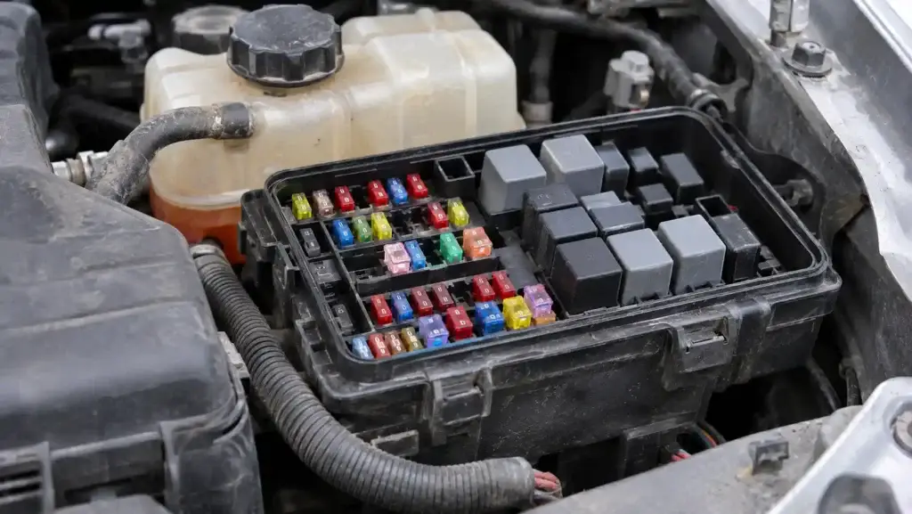
Power distribution box (under the hood)
The under-hood box holds the high-current fuses and most relays, including the power points, fuel pump relay, starter, blower motor and wipers.
- Open the hood and find the power distribution box in the engine compartment.
- Release the lid and lift it off.
- Match the positions to the table for your year below.
SVT Raptor auxiliary relay box
Raptors have an extra relay box in the left rear corner of the engine compartment. It holds the relays for the upfitter (auxiliary) switches and, from 2012, the front camera washer.
Quick reference: most-searched F-150 fuses by year
“PDB” = power distribution box under the hood. “Cabin” = passenger compartment panel.
| Circuit | 2009 | 2010 | 2011–2012 | 2013–2014 |
|---|---|---|---|---|
| Cigar lighter / front power point | PDB 22 (20A) | PDB 22 (20A) | PDB 22 (20A) | PDB 22 (20A), labeled “auxiliary power point (instrument panel)” |
| Instrument panel power point | PDB 65 (20A) | PDB 65 (20A) | PDB 65 (20A) | PDB 65 (20A) |
| Center console power point | PDB 66 (20A) | PDB 66 (20A) | PDB 66 (20A) | PDB 66 (20A) |
| Rear power point | PDB 72 (20A) | PDB 72 (20A) | PDB 72 (20A) | PDB 72 (20A) |
| 110V AC outlet | — | — | PDB 33 (40A) + cabin 38 (10A) | PDB 33 (40A) + cabin 38 (10A) |
| Radio | Cabin 39 (20A) | Cabin 39 (20A) | Cabin 29 (20A) | Cabin 29 (20A) |
| Horn | Cabin 24 (20A) | Cabin 24 (20A) | Cabin 22 (20A) | Cabin 22 (20A) |
| Fuel pump relay power | PDB 27 (20A) | PDB 27 (20A) | PDB 27 (20A) | PDB 27 (20A) |
| Starter relay | PDB 13 (30A) | PDB 13 (30A) | PDB 13 (30A) | PDB 13 (30A) |
| Blower motor | PDB 51 (40A) | PDB 51 (40A) | PDB 51 (40A) | PDB 51 (40A) |
| Wipers | PDB 49 (30A) | PDB 49 (30A) | PDB 49 (30A) | PDB 49 (30A) |
| Low-beam headlamps | Cabin 7 L / 8 R (10A) | Cabin 7 L / 8 R (10A) | Cabin 16 R / 17 L (10A) | Cabin 16 R / 17 L (10A) |
| High-beam headlamps | Cabin 23 (15A) | Cabin 23 (15A) | Cabin 39 (15A) | Cabin 39 (15A) |
| Turn signals / stop lamps | Cabin 6 (20A) | Cabin 6 (20A) | Cabin 13 R / 14 L (15A) | Cabin 13 R / 14 L (15A) |
| OBD port (data link connector) | Cabin 20 (15A) | Cabin 20 (15A) | Cabin 24 (15A) | Cabin 24 (15A) |
| Trailer brake controller | PDB 17 (30A) + cabin 33 (10A) | PDB 17 (30A) + cabin 33 (10A) | PDB 17 (30A) + cabin 37 (10A) | PDB 17 (30A) + cabin 37 (10A) |
| Trailer battery charge | PDB 21 (30A) | PDB 21 (30A) | PDB 21 (30A) | PDB 21 (30A) |
| 4×4 module | PDB 20 (20A) + 68 (20A) | PDB 20 (20A) + 68 (20A) | PDB 20 (20A) + 68 (25A) | PDB 20 (20A) + 68 (25A) |
On a 2009, Ford’s owner’s-manual chart lists fuse 22 (20A) as the cigar lighter and fuse 72 (20A) as the rear power point. One other online source puts the 2009 cigar lighter on fuse 72, so if fuse 22 is good but the lighter still has no power on a 2009, check fuse 72 too.
2009–2010 F-150 fuse box diagram: passenger side (cabin panel)
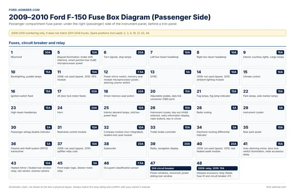
This 2010 F150 fuse panel diagram also covers the 2009 truck. The two years share one chart, and the differences are listed in the rows themselves: 2010 adds the GPS module (11), ambient lighting (14), upfitter relay coils (37) and rear heated seats (40), all spare on a 2009. Position 48 is a relay on 2009 and a 15A fuse on 2010.
On these years the horn is fuse 24, the radio is fuse 39 and the OBD port is fuse 20. All three moved in 2011.
| Fuse | Amps | Circuits protected |
|---|---|---|
| 1 | 30A | Moonroof |
| 5 | 10A | Keypad illumination, brake shift interlock, smart junction box (SJB) microprocessor power |
| 6 | 20A | Turn signals, stop lamps |
| 7 | 10A | Left low-beam headlamp |
| 8 | 10A | Right low-beam headlamp |
| 9 | 15A | Interior courtesy lights, cargo lamps |
| 10 | 15A | Backlighting, puddle lamps |
| 11 | 10A | 2009: not used (spare). 2010: GPS module |
| 12 | 7.5A | Power mirror switch, memory seat module microprocessor power, steering column switch |
| 13 | 5A | SYNC |
| 14 | 10A | 2009: not used (spare). 2010: ambient lighting module |
| 15 | 10A | Climate control |
| 16 | 15A | Ignition switch feed |
| 17 | 20A | All door lock motor feeds |
| 18 | 20A | Driver memory seat switch |
| 20 | 15A | Adjustable pedals, data link connector (OBD port) |
| 21 | 15A | Fog lamps, fog lamp indicator |
| 22 | 15A | Park lamps, side marker lamps |
| 23 | 15A | High-beam headlamps |
| 24 | 20A | Horn |
| 25 | 10A | Interior demand lamps, mid box power feed |
| 26 | 10A | Instrument cluster, key-out inhibit solenoid, radio information display, radio buttons, key-in chime |
| 28 | 5A | Radio muting |
| 29 | 5A | Instrument cluster |
| 30 | 5A | Passenger airbag disable indicator |
| 31 | 10A | Restraints control module |
| 32 | 10A | Compass module (non-integrated), heated-only seat module |
| 33 | 10A | Trailer brake controller |
| 34 | 5A | Electronic locking differential indicator |
| 35 | 10A | Rear park assist |
| 36 | 5A | Passive anti-theft system (PATS) transceiver |
| 37 | 10A | 2009: not used (spare). 2010: upfitter relay coils |
| 38 | 20A | Subwoofer |
| 39 | 20A | Radio, navigation display |
| 40 | 20A | 2009: not used (spare). 2010: rear heated seats module |
| 41 | 15A | Auto-dimming mirror, door lock switch illumination, radio accessory delay |
| 43 | 10A | Heated mirror / heated rear window relay, rain sensor, reverse camera |
| 45 | 5A | Front wiper logic, blower motor relay |
| 46 | 7.5A | Occupant classification sensor |
| 47 | 30A circuit breaker | Power windows, moonroof, power sliding rear window |
| 48 | 2009: relay. 2010: 15A | Delayed accessory relay (feeds fuse 41 and circuit breaker 47) |
Spare positions (not used): 2, 3, 4, 19, 27, 42, 44.
2011–2014 F-150 fuse box diagram: passenger side (cabin panel)
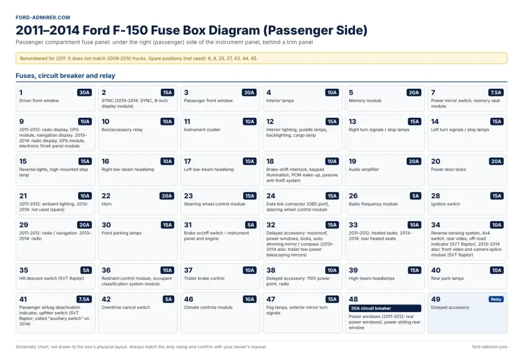
This chart covers the 2011, 2012, 2013 and 2014 F-150 passenger-side fuse panel. Every position was renumbered from 2010: the horn is now fuse 22, the radio fuse 29, the OBD port fuse 24 and the high beams fuse 39. Year-specific differences are written into the rows, such as fuse 21 (ambient lighting on 2011–2012, spare on 2013–2014).
Use this 2014 F150 fuse panel diagram for a 2013 or 2014 too; Ford kept the same numbering through the end of the generation.
| Fuse | Amps | Circuits protected |
|---|---|---|
| 1 | 30A | Driver front window |
| 2 | 15A | SYNC (2013–2014: SYNC, 8-inch display module) |
| 3 | 30A | Passenger front window |
| 4 | 10A | Interior lamps |
| 5 | 20A | Memory module |
| 7 | 7.5A | Power mirror switch, memory seat module |
| 9 | 10A | 2011–2012: radio display, GPS module, navigation display. 2013–2014: radio display, GPS module, electronic finish panel module |
| 10 | 10A | Run/accessory relay |
| 11 | 10A | Instrument cluster |
| 12 | 15A | Interior lighting, puddle lamps, backlighting, cargo lamp |
| 13 | 15A | Right turn signals / stop lamps |
| 14 | 15A | Left turn signals / stop lamps |
| 15 | 15A | Reverse lights, high-mounted stop lamp |
| 16 | 10A | Right low-beam headlamp |
| 17 | 10A | Left low-beam headlamp |
| 18 | 10A | Brake-shift interlock, keypad illumination, PCM wake-up, passive anti-theft system |
| 19 | 20A | Audio amplifier |
| 20 | 20A | Power door locks |
| 21 | 10A | 2011–2012: ambient lighting. 2013–2014: not used (spare) |
| 22 | 20A | Horn |
| 23 | 15A | Steering wheel control module |
| 24 | 15A | Data link connector (OBD port), steering wheel control module |
| 26 | 5A | Radio frequency module |
| 28 | 15A | Ignition switch |
| 29 | 20A | 2011–2012: radio / navigation. 2013–2014: radio |
| 30 | 15A | Front parking lamps |
| 31 | 5A | Brake on/off switch – instrument panel and engine |
| 32 | 15A | Delayed accessory: moonroof, power windows, locks, auto-dimming mirror / compass (2013–2014 also: trailer tow power telescoping mirrors) |
| 33 | 10A | 2011–2012: heated seats. 2013–2014: rear heated seats |
| 34 | 10A | Reverse sensing system, 4×4 switch, rear video, off-road indicator (SVT Raptor). 2013–2014 also: front video and camera splice module (SVT Raptor) |
| 35 | 5A | Hill descent switch (SVT Raptor) |
| 36 | 10A | Restraint control module, occupant classification system module |
| 37 | 10A | Trailer brake control |
| 38 | 10A | Delayed accessory: 110V power point, radio |
| 39 | 15A | High-beam headlamps |
| 40 | 10A | Rear park lamps |
| 41 | 7.5A | Passenger airbag deactivation indicator, upfitter switch (SVT Raptor; called “auxiliary switch” on 2014) |
| 42 | 5A | Overdrive cancel switch |
| 46 | 10A | Climate controls module |
| 47 | 15A | Fog lamps, exterior mirror turn signals |
| 48 | 30A circuit breaker | Power windows (2011–2012: rear power windows), power sliding rear window |
| 49 | Relay | Delayed accessory |
Spare positions (not used): 6, 8, 25, 27, 43, 44, 45.
2009 Ford F-150 fuse box diagram: under the hood
The 2009 Ford F150 fuse box diagram for the engine compartment has the fewest circuits of the generation: no electric fan or upfitter circuits yet. The power points are here, not in the cab: cigar lighter fuse 22, instrument panel power point 65, console 66 and rear 72, all 20A.
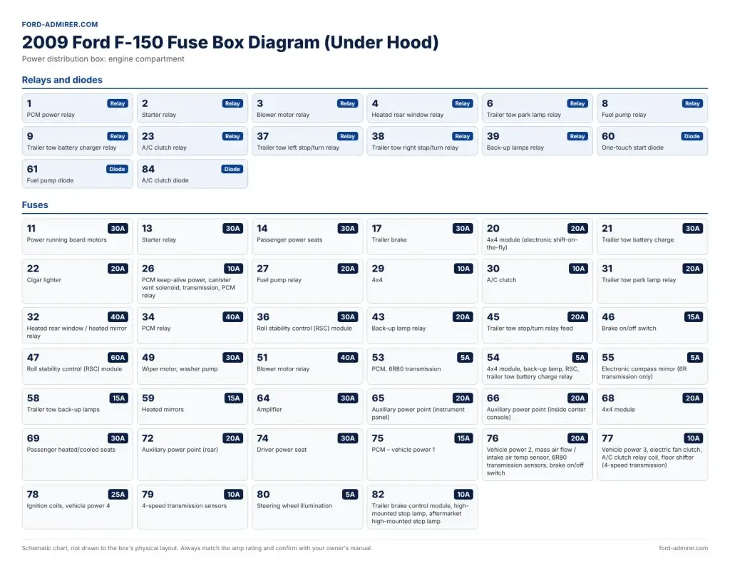
2009 relays
| Position | Relay |
|---|---|
| 1 | PCM power relay |
| 2 | Starter relay |
| 3 | Blower motor relay |
| 4 | Heated rear window relay |
| 6 | Trailer tow park lamp relay |
| 8 | Fuel pump relay |
| 9 | Trailer tow battery charger relay |
| 23 | A/C clutch relay |
| 37 | Trailer tow left stop/turn relay |
| 38 | Trailer tow right stop/turn relay |
| 39 | Back-up lamps relay |
| 60 | One-touch start diode |
| 61 | Fuel pump diode |
| 84 | A/C clutch diode |
2009 fuses
| Fuse | Amps | Circuits protected |
|---|---|---|
| 11 | 30A | Power running board motors |
| 13 | 30A | Starter relay |
| 14 | 30A | Passenger power seats |
| 17 | 30A | Trailer brake |
| 20 | 20A | 4×4 module (electronic shift-on-the-fly) |
| 21 | 30A | Trailer tow battery charge |
| 22 | 20A | Cigar lighter |
| 26 | 10A | PCM keep-alive power, canister vent solenoid, transmission, PCM relay |
| 27 | 20A | Fuel pump relay |
| 29 | 10A | 4×4 |
| 30 | 10A | A/C clutch |
| 31 | 20A | Trailer tow park lamp relay |
| 32 | 40A | Heated rear window / heated mirror relay |
| 34 | 40A | PCM relay |
| 36 | 30A | Roll stability control (RSC) module |
| 43 | 20A | Back-up lamp relay |
| 45 | 20A | Trailer tow stop/turn relay feed |
| 46 | 15A | Brake on/off switch |
| 47 | 60A | Roll stability control (RSC) module |
| 49 | 30A | Wiper motor, washer pump |
| 51 | 40A | Blower motor relay |
| 53 | 5A | PCM, 6R80 transmission |
| 54 | 5A | 4×4 module, back-up lamp, RSC, trailer tow battery charge relay |
| 55 | 5A | Electronic compass mirror (6R transmission only) |
| 58 | 15A | Trailer tow back-up lamps |
| 59 | 15A | Heated mirrors |
| 64 | 30A | Amplifier |
| 65 | 20A | Auxiliary power point (instrument panel) |
| 66 | 20A | Auxiliary power point (inside center console) |
| 68 | 20A | 4×4 module |
| 69 | 30A | Passenger heated/cooled seats |
| 72 | 20A | Auxiliary power point (rear) |
| 74 | 30A | Driver power seat |
| 75 | 15A | PCM – vehicle power 1 |
| 76 | 20A | Vehicle power 2, mass air flow / intake air temp sensor, 6R80 transmission sensors, brake on/off switch |
| 77 | 10A | Vehicle power 3, electric fan clutch, A/C clutch relay coil, floor shifter (4-speed transmission) |
| 78 | 25A | Ignition coils, vehicle power 4 |
| 79 | 10A | 4-speed transmission sensors |
| 80 | 5A | Steering wheel illumination |
| 82 | 10A | Trailer brake control module, high-mounted stop lamp, aftermarket high-mounted stop lamp |
2010 Ford F-150 fuse box diagram: under the hood
The 2010 Ford F150 fuse box diagram for the engine bay keeps 2009’s numbering but adds electric fan circuits (fuses 12, 15 and 63) and upfitter circuits (fuses 18, 19, 28 and 44, with relays 7, 10, 24 and 62). The ignition coil fuse 78 drops from 25A to 15A, and heated mirrors move from fuse 59 to fuse 41.
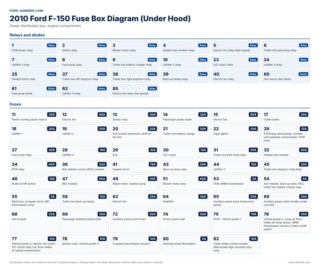
2010 relays
| Position | Relay |
|---|---|
| 1 | PCM power relay |
| 2 | Starter relay |
| 3 | Blower motor relay |
| 4 | Heated rear window relay |
| 5 | Electric fan relay (high speed) |
| 6 | Trailer tow park lamp relay |
| 7 | Upfitter 1 relay |
| 8 | Fuel pump relay |
| 9 | Trailer tow battery charger relay |
| 10 | Upfitter 2 relay |
| 23 | A/C clutch relay |
| 24 | Upfitter 4 relay |
| 25 | Heated mirror relay |
| 37 | Trailer tow left stop/turn relay |
| 38 | Trailer tow right stop/turn relay |
| 39 | Back-up lamps relay |
| 40 | Electric fan relay |
| 60 | One-touch start diode |
| 61 | Fuel pump diode |
| 62 | Upfitter 3 relay |
| 85 | Electric fan relay (low speed) |
2010 fuses
| Fuse | Amps | Circuits protected |
|---|---|---|
| 11 | 30A | Power running board motors |
| 12 | 40A | Electric fan |
| 13 | 30A | Starter relay |
| 14 | 30A | Passenger power seats |
| 15 | 40A | Electric fan |
| 17 | 30A | Trailer brake |
| 18 | 30A | Upfitter 1 |
| 19 | 30A | Upfitter 2 |
| 20 | 20A | 4×4 module (electronic shift-on-the-fly) |
| 21 | 30A | Trailer tow battery charge |
| 22 | 20A | Cigar lighter |
| 26 | 10A | PCM keep-alive power, canister vent solenoid, transmission, PCM relay |
| 27 | 20A | Fuel pump relay |
| 28 | 10A | Upfitter 4 |
| 29 | 10A | 4×4 |
| 30 | 10A | A/C clutch |
| 31 | 20A | Trailer tow park lamp relay |
| 32 | 40A | Heated rear window |
| 34 | 40A | PCM relay |
| 36 | 30A | Roll stability control (RSC) module |
| 41 | 15A | Heated mirror |
| 43 | 20A | Back-up lamp relay |
| 44 | 15A | Upfitter 3 |
| 45 | 20A | Trailer tow stop/turn relay feed |
| 46 | 15A | Brake on/off switch |
| 47 | 60A | RSC module |
| 49 | 30A | Wiper motor, washer pump |
| 51 | 40A | Blower motor relay |
| 53 | 5A | PCM, 6R80 transmission |
| 54 | 5A | 4×4 module, back-up lamp, RSC, trailer tow battery charge relay |
| 55 | 5A | Electronic compass mirror (6R transmission only) |
| 58 | 15A | Trailer tow back-up lamps |
| 63 | 25A | Electric fan |
| 64 | 30A | Amplifier |
| 65 | 20A | Auxiliary power point (instrument panel) |
| 66 | 20A | Auxiliary power point (inside center console) |
| 68 | 20A | 4×4 module |
| 69 | 30A | Passenger heated/cooled seats |
| 72 | 20A | Auxiliary power point (rear) |
| 74 | 30A | Driver power seat |
| 75 | 15A | PCM – vehicle power 1 |
| 76 | 20A | Vehicle power 2, mass air flow / intake air temp sensor, 6R80 transmission sensors, brake on/off switch |
| 77 | 10A | Vehicle power 3, electric fan clutch, A/C clutch relay coil, floor shifter (4-speed transmission) |
| 78 | 15A | Ignition coils, vehicle power 4 |
| 79 | 10A | 4-speed transmission sensors |
| 80 | 5A | Steering wheel illumination |
| 82 | 10A | Trailer brake control module, aftermarket high-mounted stop lamp |
2011–2012 Ford F-150 fuse box diagram: under the hood
This is the 2011 Ford F150 fuse box diagram under the hood, and the 2012 fuse box diagram under the hood is the same apart from three rows (fuses 32, 41 and 54). The new engines brought new circuits: the 110V AC outlet (fuse 33, 40A), a separate PCM relay for the 3.5L EcoBoost (relay 10) and its vacuum pump (relay 25, fuse 64). Several fuses also change rating by engine, so check your engine before buying a replacement.
If you’re chasing an EcoBoost-specific fault, these are the 3.5L rows to look at: PCM relay power 34 (50A), PCM vehicle power 1 fuse 75 (25A) and vacuum pump fuse 64 (40A). For the engine’s wider issues, see our guide to 3.5 EcoBoost problems.
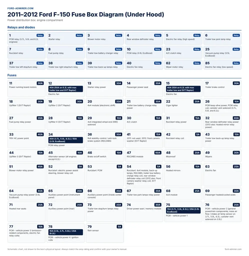
2011–2012 relays
| Position | Relay |
|---|---|
| 1 | PCM relay (3.7L, 5.0L and 6.2L engines) |
| 2 | Starter relay |
| 3 | Blower motor relay |
| 4 | Rear window defroster relay |
| 5 | Electric fan relay (high speed) |
| 6 | Trailer tow park lamp relay |
| 7 | Run/start relay |
| 8 | Fuel pump relay |
| 9 | Trailer tow battery charger relay |
| 10 | PCM relay (3.5L EcoBoost) |
| 23 | A/C clutch relay |
| 25 | Vacuum pump relay (3.5L EcoBoost) |
| 37 | Trailer tow left stop/turn relay |
| 38 | Trailer tow right stop/turn relay |
| 39 | Trailer tow back-up lamps relay |
| 40 | Electric fan relay |
| 62 | Wiper motor relay |
| 85 | Electric fan relay (low speed) |
2011–2012 fuses
| Fuse | Amps | Circuits protected |
|---|---|---|
| 11 | 30A | Power running board motors |
| 12 | 40A (50A on 6.2L with max trailer tow and SVT Raptor) | Electric fan |
| 13 | 30A | Starter relay power |
| 14 | 30A | Passenger power seat |
| 15 | 40A (50A on 6.2L with max trailer tow and SVT Raptor) | Electric fan |
| 17 | 30A | Trailer brake control |
| 18 | 30A | Upfitter 1 (SVT Raptor) |
| 19 | 30A | Upfitter 2 (SVT Raptor) |
| 20 | 20A | 4×4 module (electronic shift) |
| 21 | 30A | Trailer tow battery charge relay power |
| 22 | 20A | Cigar lighter |
| 26 | 10A | PCM keep-alive power, PCM relay coil, canister vent solenoid (3.7L, 5.0L and 6.2L) |
| 27 | 20A | Fuel pump relay power |
| 28 | 10A | Upfitter 4 (SVT Raptor) |
| 29 | 10A | 4×4 integrated wheel end (IWE) solenoid |
| 30 | 10A | A/C clutch |
| 31 | 15A | Run/start relay power |
| 32 | 40A | Rear window defroster relay power (2012 also: heated mirror relay power) |
| 33 | 40A | 110V AC power point |
| 34 | 40A (3.7L, 5.0L, 6.2L) / 50A (3.5L EcoBoost) | PCM relay power |
| 36 | 30A | Roll stability control / anti-lock brake system (RSC/ABS) |
| 41 | 15A | 2011: not used. 2012: front camera washer (SVT Raptor) |
| 42 | 5A | Run/start relay coil |
| 43 | 15A | Trailer tow back-up lamp relay power |
| 44 | 15A | Upfitter 3 (SVT Raptor) |
| 45 | 10A | Alternator sensor (all engines except 6.2L) |
| 46 | 10A | Brake on/off switch |
| 47 | 60A | RSC/ABS module |
| 48 | 20A | Moonroof |
| 49 | 30A | Wipers |
| 51 | 40A | Blower motor relay power |
| 52 | 5A | Run/start: electric power assist steering, blower relay coil |
| 53 | 5A | Run/start: PCM |
| 54 | 5A | Run/start: 4×4 module, back-up lamps, RSC/ABS, trailer tow battery charge relay coil, rear window defroster relay coil (2012 also: front camera washer relay coil, SVT Raptor) |
| 56 | 15A | Heated mirrors |
| 63 | 25A | Electric fan |
| 64 | 40A | Vacuum pump relay power (3.5L EcoBoost) |
| 65 | 20A | Auxiliary power point (instrument panel) |
| 66 | 20A | Auxiliary power point (inside center console) |
| 67 | 20A | Trailer tow park lamps relay power |
| 68 | 25A | 4×4 module |
| 69 | 30A | Passenger heated/cooled seats |
| 71 | 20A | Heated rear seats |
| 72 | 20A | Auxiliary power point (rear) |
| 73 | 20A | Trailer tow stop/turn lamps relay power |
| 74 | 30A | Driver power seat / memory module |
| 75 | 15A (3.7L, 5.0L, 6.2L) / 25A (3.5L EcoBoost) | PCM – vehicle power 1 |
| 76 | 20A | PCM – vehicle power 2 (general powertrain components; mass air flow / intake air temp sensor on 3.7L, 5.0L, 6.2L; canister vent solenoid on 3.5L) |
| 77 | 10A | PCM – vehicle power 3 (emission-related components, electric fan relay coils) |
| 78 | 15A (3.5L, 3.7L, 5.0L) / 20A (6.2L) | PCM – vehicle power 4: ignition coils |
| 79 | 5A | Rain sensor |
2013–2014 Ford F-150 fuse box diagram: under the hood
The 2013 Ford F150 fuse box diagram and the 2014 chart share this under-hood layout. New for these years: fuses 16 and 35 (20A each) feed the HID headlamps, and fuse 22 is now labeled “auxiliary power point (instrument panel)” rather than cigar lighter. The vacuum pump relay and fuse from 2011–2012 are no longer listed. On 2014 trucks, the SVT Raptor “upfitter” circuits are called “auxiliary switch” circuits.
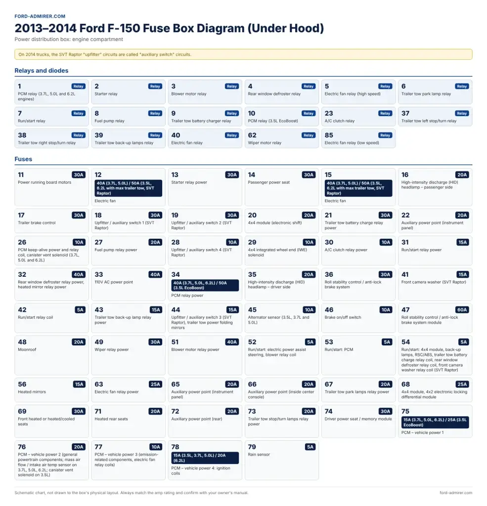
2013–2014 relays
| Position | Relay |
|---|---|
| 1 | PCM relay (3.7L, 5.0L and 6.2L engines) |
| 2 | Starter relay |
| 3 | Blower motor relay |
| 4 | Rear window defroster relay |
| 5 | Electric fan relay (high speed) |
| 6 | Trailer tow park lamp relay |
| 7 | Run/start relay |
| 8 | Fuel pump relay |
| 9 | Trailer tow battery charger relay |
| 10 | PCM relay (3.5L EcoBoost) |
| 23 | A/C clutch relay |
| 37 | Trailer tow left stop/turn relay |
| 38 | Trailer tow right stop/turn relay |
| 39 | Trailer tow back-up lamps relay |
| 40 | Electric fan relay |
| 62 | Wiper motor relay |
| 85 | Electric fan relay (low speed) |
2013–2014 fuses
| Fuse | Amps | Circuits protected |
|---|---|---|
| 11 | 30A | Power running board motors |
| 12 | 40A (3.7L, 5.0L) / 50A (3.5L, 6.2L with max trailer tow, SVT Raptor) | Electric fan |
| 13 | 30A | Starter relay power |
| 14 | 30A | Passenger power seat |
| 15 | 40A (3.7L, 5.0L) / 50A (3.5L, 6.2L with max trailer tow, SVT Raptor) | Electric fan |
| 16 | 20A | High-intensity discharge (HID) headlamp – passenger side |
| 17 | 30A | Trailer brake control |
| 18 | 30A | Upfitter / auxiliary switch 1 (SVT Raptor) |
| 19 | 30A | Upfitter / auxiliary switch 2 (SVT Raptor) |
| 20 | 20A | 4×4 module (electronic shift) |
| 21 | 30A | Trailer tow battery charge relay power |
| 22 | 20A | Auxiliary power point (instrument panel) |
| 26 | 10A | PCM keep-alive power and relay coil, canister vent solenoid (3.7L, 5.0L and 6.2L) |
| 27 | 20A | Fuel pump relay power |
| 28 | 10A | Upfitter / auxiliary switch 4 (SVT Raptor) |
| 29 | 10A | 4×4 integrated wheel end (IWE) solenoid |
| 30 | 10A | A/C clutch relay power |
| 31 | 15A | Run/start relay power |
| 32 | 40A | Rear window defroster relay power, heated mirror relay power |
| 33 | 40A | 110V AC power point |
| 34 | 40A (3.7L, 5.0L, 6.2L) / 50A (3.5L EcoBoost) | PCM relay power |
| 35 | 20A | High-intensity discharge (HID) headlamp – driver side |
| 36 | 30A | Roll stability control / anti-lock brake system |
| 41 | 15A | Front camera washer (SVT Raptor) |
| 42 | 5A | Run/start relay coil |
| 43 | 15A | Trailer tow back-up lamp relay power |
| 44 | 15A | Upfitter / auxiliary switch 3 (SVT Raptor), trailer tow power folding mirrors |
| 45 | 10A | Alternator sensor (3.5L, 3.7L and 5.0L) |
| 46 | 10A | Brake on/off switch |
| 47 | 60A | Roll stability control / anti-lock brake system module |
| 48 | 20A | Moonroof |
| 49 | 30A | Wiper relay power |
| 51 | 40A | Blower motor relay power |
| 52 | 5A | Run/start: electric power assist steering, blower relay coil |
| 53 | 5A | Run/start: PCM |
| 54 | 5A | Run/start: 4×4 module, back-up lamps, RSC/ABS, trailer tow battery charge relay coil, rear window defroster relay coil, front camera washer relay coil (SVT Raptor) |
| 56 | 15A | Heated mirrors |
| 63 | 25A | Electric fan relay power |
| 65 | 20A | Auxiliary power point (instrument panel) |
| 66 | 20A | Auxiliary power point (inside center console) |
| 67 | 20A | Trailer tow park lamps relay power |
| 68 | 25A | 4×4 module, 4×2 electronic locking differential module |
| 69 | 30A | Front heated or heated/cooled seats |
| 71 | 20A | Heated rear seats |
| 72 | 20A | Auxiliary power point (rear) |
| 73 | 20A | Trailer tow stop/turn lamps relay power |
| 74 | 30A | Driver power seat / memory module |
| 75 | 15A (3.7L, 5.0L, 6.2L) / 25A (3.5L EcoBoost) | PCM – vehicle power 1 |
| 76 | 20A | PCM – vehicle power 2 (general powertrain components; mass air flow / intake air temp sensor on 3.7L, 5.0L, 6.2L; canister vent solenoid on 3.5L) |
| 77 | 10A | PCM – vehicle power 3 (emission-related components, electric fan relay coils) |
| 78 | 15A (3.5L, 3.7L, 5.0L) / 20A (6.2L) | PCM – vehicle power 4: ignition coils |
| 79 | 5A | Rain sensor |
SVT Raptor auxiliary relay box (2011–2014)
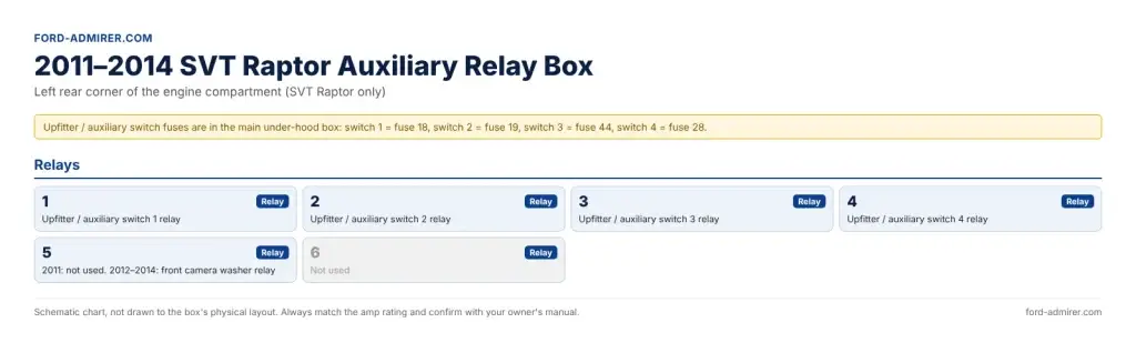
The SVT Raptor auxiliary relay box sits in the left rear corner of the engine compartment. It holds the relays for the four upfitter switches (called auxiliary switches on 2014); their fuses (18, 19, 44 and 28) are in the main under-hood box.
[custom diagram: SVT Raptor auxiliary relay box]
| Position | Relay |
|---|---|
| 1 | Upfitter / auxiliary switch 1 relay |
| 2 | Upfitter / auxiliary switch 2 relay |
| 3 | Upfitter / auxiliary switch 3 relay |
| 4 | Upfitter / auxiliary switch 4 relay |
| 5 | 2011: not used. 2012–2014: front camera washer relay |
| 6 | Not used |
If an accessory wired to an upfitter switch stops working, check its fuse in the under-hood box first (switch 1 = fuse 18, switch 2 = fuse 19, switch 3 = fuse 44, switch 4 = fuse 28), then the matching relay here.
How to check and replace a blown fuse
A blown fuse takes about five minutes to find and swap, as long as you replace it with the exact same amp rating.
What you need: a fuse puller or needle-nose pliers, a 12V test light or multimeter, a flashlight, and spare mini and cartridge fuses in the ratings from your year’s table.
- Find the right fuse. Check the quick reference first, then your year’s full table. Note which box it’s in (cabin or under-hood), the number and the amp rating.
- Test it in place (fastest). With the key in RUN, clip a test light to bare metal and touch the two small test points on top of the fuse. Light on both sides = good. Light on one side only = blown. A multimeter set to DC volts does the same: about 12 volts on both sides means the fuse is fine.
- Switch off and pull it. Turn the ignition off, then pull the fuse straight out with the puller.
- Look at it. A blown mini fuse has a broken metal strip inside the plastic. On a cartridge fuse, look through the clear window on top. A multimeter on continuity confirms it if you can’t tell.
- Fit an identical fuse. Same type, same amp rating, pushed fully into the slot. Where a table lists two ratings by engine, use the one for your engine.
- Refit the cover and test. The cabin cover goes on top first, then push the bottom until it clicks. Turn the key on and check the circuit works.
Never fit a higher-rated fuse. The fuse is sized for the wire behind it. A bigger fuse lets the wire overheat instead of the fuse blowing, which is how harness damage and fires start.
If the new fuse blows straight away, stop swapping fuses. Something on that circuit is shorted, often a pinched wire, a failed motor or a faulty accessory in a power point. Tracing a short properly needs the full wiring diagrams, which are in the 2009–2014 Ford F-150 workshop manual, not the owner’s manual.
Common 12th-gen F-150 fuse problems (and the exact fuse)
These are the fuse problems 2009–2014 owners search for most. “PDB” means the under-hood box; “cabin” means the passenger-side panel.
Power outlet or cigarette lighter dead
All the 12V outlets are fused under the hood, not in the cab, on every year from 2009 to 2014:
- Cigar lighter / front power point: PDB 22 (20A)
- Instrument panel power point: PDB 65 (20A)
- Center console power point: PDB 66 (20A)
- Rear power point: PDB 72 (20A)
- 110V AC outlet (2011–2014): PDB 33 (40A) plus cabin 38 (10A)
On a 2009, if fuse 22 is good but the lighter is still dead, check fuse 72 as well. A power point fuse that keeps blowing usually means a coin or a faulty charger in the socket.
Radio out
The main radio fuse is cabin 39 (20A) on 2009–2010 and cabin 29 (20A) on 2011–2014. If that’s good, check the radio’s other feeds: cabin 41 (15A, radio accessory delay) and 26 (10A) on 2009–2010, or cabin 9 (10A, radio display) and 38 (10A, delayed accessory radio) on 2011–2014. No sound with a working display can mean the amplifier: PDB 64 (30A) on 2009–2010, cabin 19 (20A) on 2011–2014.
Horn not working
The horn is cabin 24 (20A) on 2009–2010 and cabin 22 (20A) on 2011–2014. This is the classic renumbering trap: on a 2011–2014 truck, fuse 24 is the OBD port, not the horn.
No start or fuel pump not running
- Cranks but won’t start: fuel pump relay power PDB 27 (20A) on every year, with the fuel pump relay in PDB position 8. Then check the PCM fuses: PDB 34 (PCM relay power) and 75 (PCM vehicle power 1), whose ratings vary by engine on 2011–2014.
- No crank at all: starter relay PDB 13 (30A), with the starter relay in PDB position 2. Also check the ignition switch fuse: cabin 16 (15A) on 2009–2010, cabin 28 (15A) on 2011–2014.
- Key not recognized: the passive anti-theft (PATS) fuse is cabin 36 (5A) on 2009–2010 and cabin 18 (10A) on 2011–2014.
If the fuses and relays check out, the fault is elsewhere. For the problems each model year is known for, see our guide to the best F-150 years.
Trailer lights or trailer brake not working
- Trailer brake controller: PDB 17 (30A) plus cabin 33 (10A) on 2009–2010, or cabin 37 (10A) on 2011–2014
- Trailer battery charge: PDB 21 (30A)
- Trailer park lamps: PDB 31 (20A) on 2009–2010, PDB 67 (20A) on 2011–2014
- Trailer stop/turn: PDB 45 (20A) on 2009–2010, PDB 73 (20A) on 2011–2014, with the left and right stop/turn relays in PDB positions 37 and 38
- Trailer back-up lamps: PDB 43 (20A) and 58 (15A) on 2009–2010, PDB 43 (15A) on 2011–2014
4×4 not engaging
- 4×4 module: PDB 20 (20A) plus PDB 68 (20A on 2009–2010, 25A on 2011–2014)
- 4×4 / integrated wheel end (IWE) solenoid: PDB 29 (10A)
- 4×4 switch (2011–2014): cabin 34 (10A)
If all of these are good, the fault is in the 4×4 hardware itself (module, switch, wiring or the front hubs) rather than a fuse.
Before chasing any electrical fault, run your VIN through the NHTSA recall lookup to see whether an open recall covers it.
FAQs
Where is the fuse box on a 2011 Ford F-150?
A 2011 F-150 has two: the passenger compartment fuse panel under the right (passenger) side of the instrument panel, behind a trim panel, and the power distribution box under the hood. SVT Raptors also have a small auxiliary relay box in the left rear corner of the engine compartment. The cabin panel is not left of the steering wheel; that was the 1997–2003 truck.
Is there a fuse box under the hood on a 2013 F-150?
Yes. The power distribution box in the engine compartment holds the high-current fuses and most relays, including all four 12V power points (fuses 22, 65, 66 and 72), the 110V outlet (fuse 33), the fuel pump relay, starter, blower motor, wipers and the HID headlamp fuses (16 and 35).
Which fuse is the cigarette lighter on a 2009–2014 F-150?
Fuse 22 (20A) in the under-hood power distribution box on every year. On 2013–2014 Ford labels the same fuse “auxiliary power point (instrument panel)”. Fuse 72 (20A) is the rear power point. On a 2009, if fuse 22 is good but the lighter is dead, check fuse 72 too.
Which fuse is the fuel pump on a 2012 F-150?
Fuse 27 (20A) in the under-hood box, labeled “fuel pump relay power”. The fuel pump relay itself is in position 8 of the same box. The fuse number is the same on every 2009–2014 truck.
Why doesn’t my 2010 F-150 match a 2011 fuse diagram?
Ford completely renumbered the passenger compartment panel for 2011. On a 2010 the horn is cabin fuse 24, the radio 39 and the OBD port 20; on a 2011 the horn is 22, the radio 29 and the OBD port 24. The under-hood box kept its numbering, though some circuits changed. Always use the chart for your exact year.
Is there a 2011 F-150 fuse box diagram PDF?
Yes: Ford’s official fuse charts are in the owner’s manual, which you can look up by year and model on Ford’s owner manual site. The tables on this page follow those owner’s-manual charts.
Images: what to upload and where (not for publishing)
This page needs 12 images: 7 fuse diagrams (already made, sent in chat), 4 photos and 1 featured image (made from the prompts below). Upload each image in place of its marker in the article, then delete the marker.