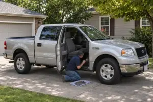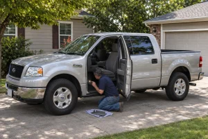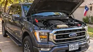

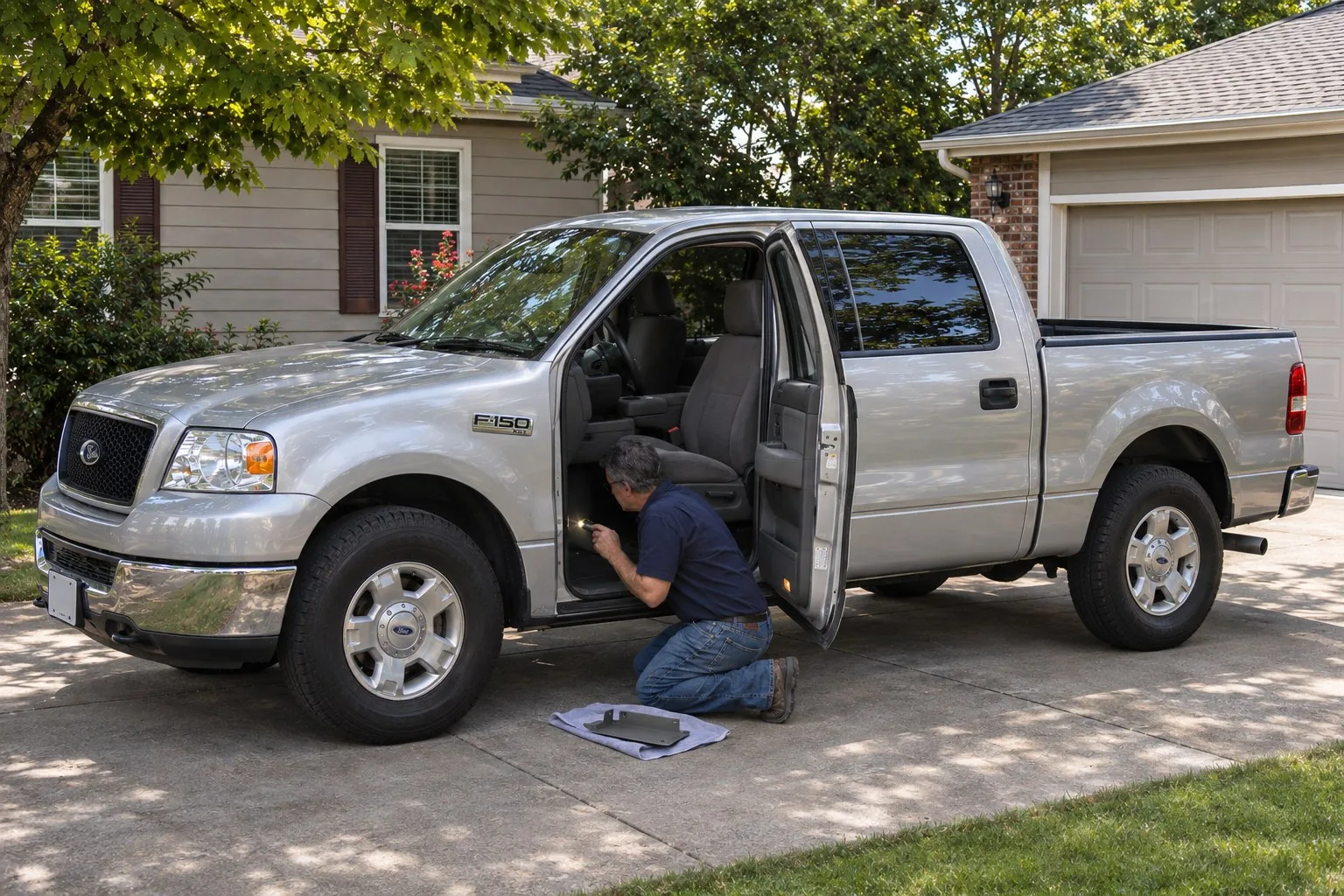
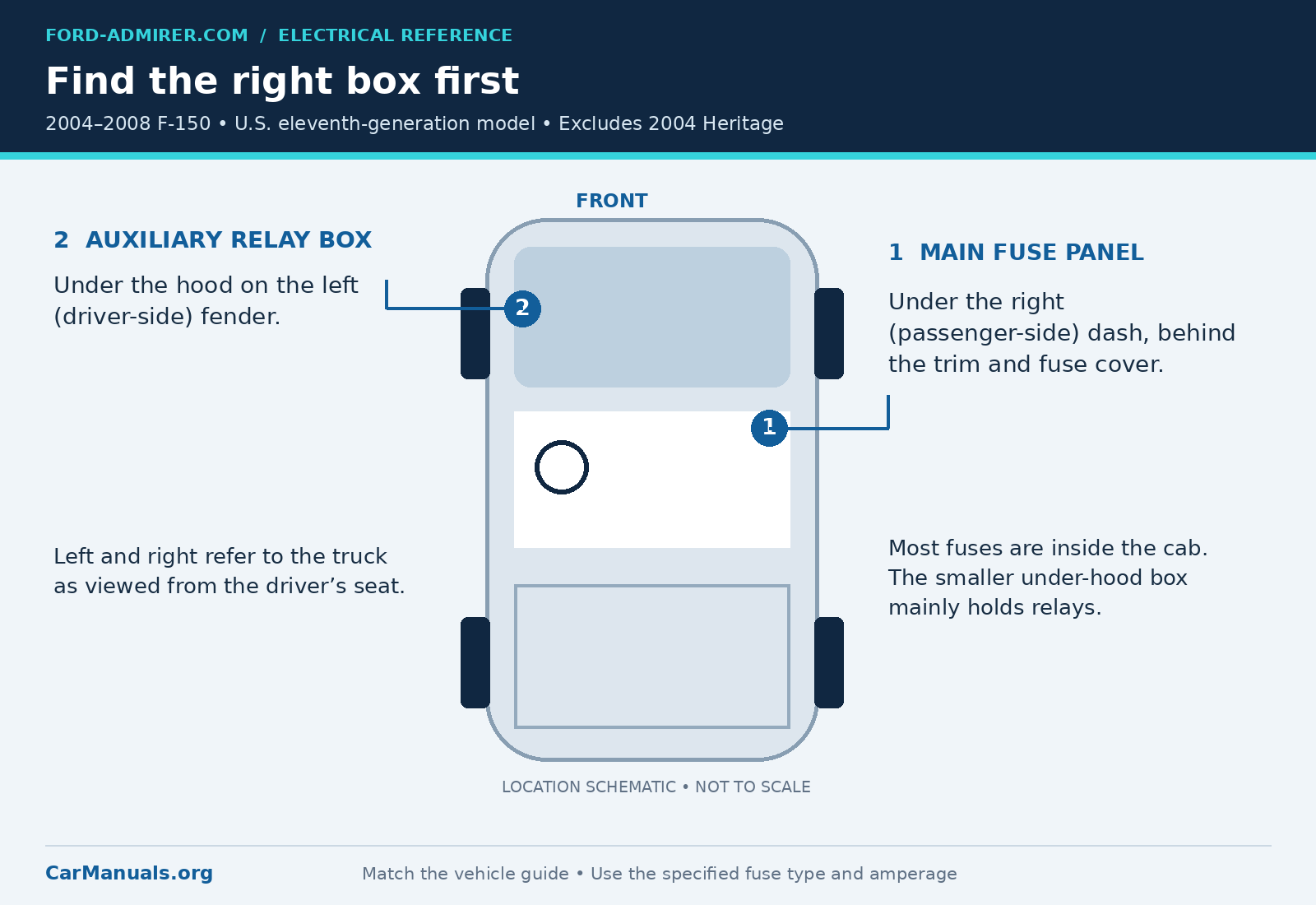
A dead power socket, silent radio or no-start problem can send you straight to the fuse panel. On the 2004-2008 Ford F-150, the main panel is under the passenger side of the dash. A smaller auxiliary relay box sits under the hood on the driver-side fender.
Start with the model year, then match the fuse number, rating and circuit. Similar-looking panels do not make the assignments interchangeable. This guide covers the U.S. eleventh-generation F-150, not the previous-generation 2004 F-150 Heritage.
Working on a different generation? See our F-150 fuse box diagram for every year.
Common fuses at a glance
These positions are in the passenger compartment panel. Values follow the Ford guide editions linked at the end.
| Circuit | 2004-2005 | 2006 | 2007-2008 |
|---|---|---|---|
| Cigar lighter and OBD power | 41 • 20A | 41 • 20A | 110 • 20A |
| Instrument panel power point | 39 • 20A | 39 • 20A | 117 • 20A |
| Rear power point | 37 • 20A | 37 • 20A | 37 • 20A |
| Radio main power | 31 • 20A | 31 • 20A | 31 • 20A |
| Fuel pump relay | No dedicated listing | 9 • 20A | 9 • 20A |
| Fuel injectors | 34 • 20A | 9 • 20A | 9 • 20A |
| PCM main power | 34 • 20A | 34 • 15A | 34 • 15A |
| Horn | 26 • 20A | 26 • 20A | 26 • 20A |
| Starter solenoid | 101 • 30A | 101 • 30A | 101 • 30A |
| Blower motor | 116 • 30A | 116 • 30A | 116 • 30A |
| Wipers and washer pump | 113 • 30A | 113 • 30A | 113 • 30A |
| Trailer electric brakes | 105 • 30A | 105 • 30A | 105 • 30A |
| Trailer battery charge | 106 • 30A | 106 • 30A | 106 • 30A |
| Power windows | 401 • 30A breaker | 401 • 30A breaker | 401 • 30A breaker |
For 2004-2005, the owner’s guides do not list a separate fuel pump fuse. Fuse 34 supplies the fuel injectors and PCM. To trace the pump feed itself, use the wiring diagram for the exact truck.
Where the fuse boxes are
To access the main panel, remove the trim below the right-hand side of the instrument panel, then remove the fuse cover using its PULL tab. When refitting it, engage the upper part first, then press the lower part until it clicks into place. Make sure it is secure.
The auxiliary relay box is on the left fender in the engine compartment. Left and right are described from the seated driver’s perspective. The same relay number can appear in both boxes, so identify the box before using a relay label.
Why the lighter fuse can be confusing
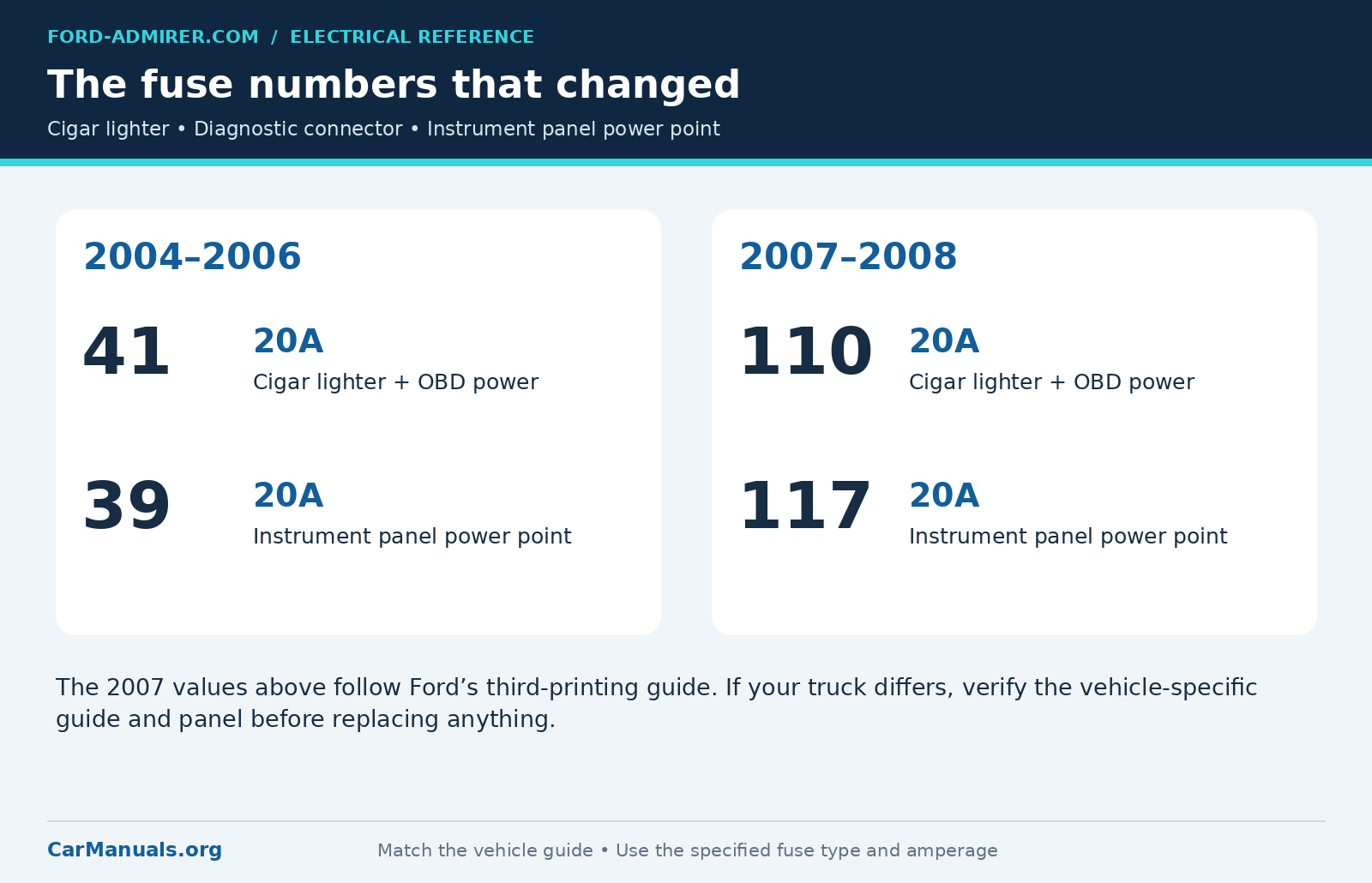
The cited 2004-2006 guides place the cigar lighter and diagnostic connector on fuse 41, a 20A mini fuse. Ford’s 2007 third-printing guide and 2008 first-printing guide use fuse 110, a 20A cartridge fuse. The instrument panel power point similarly changes from fuse 39 to fuse 117.
Some 2007 trucks and earlier printings of the 2007 guide still use fuse 41 for the lighter and fuse 39 for the power point. If your truck’s guide or fuse panel shows that layout, follow it. An empty position 110 alone does not prove which version you have, because a fuse may simply have been removed, so do not fill an empty slot to experiment.
How to read the diagrams
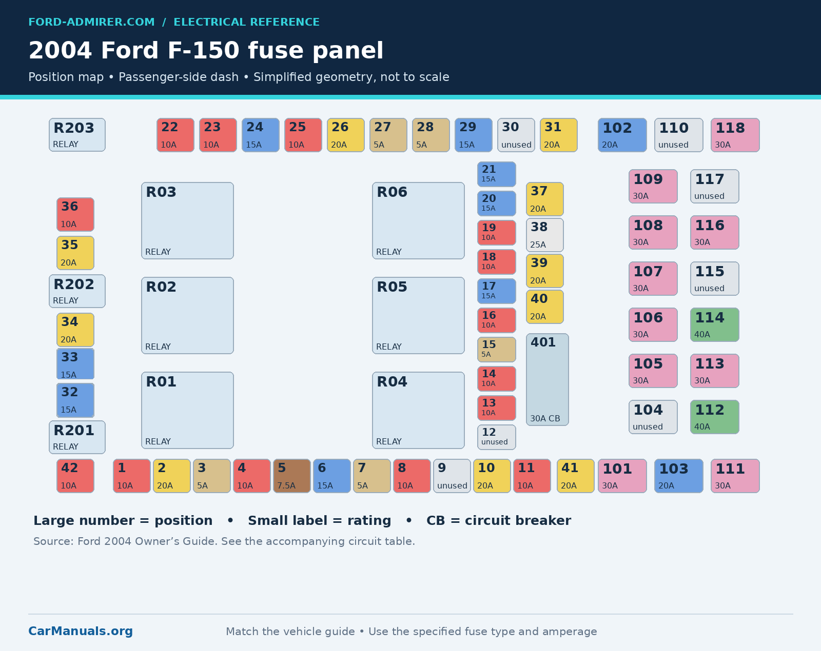
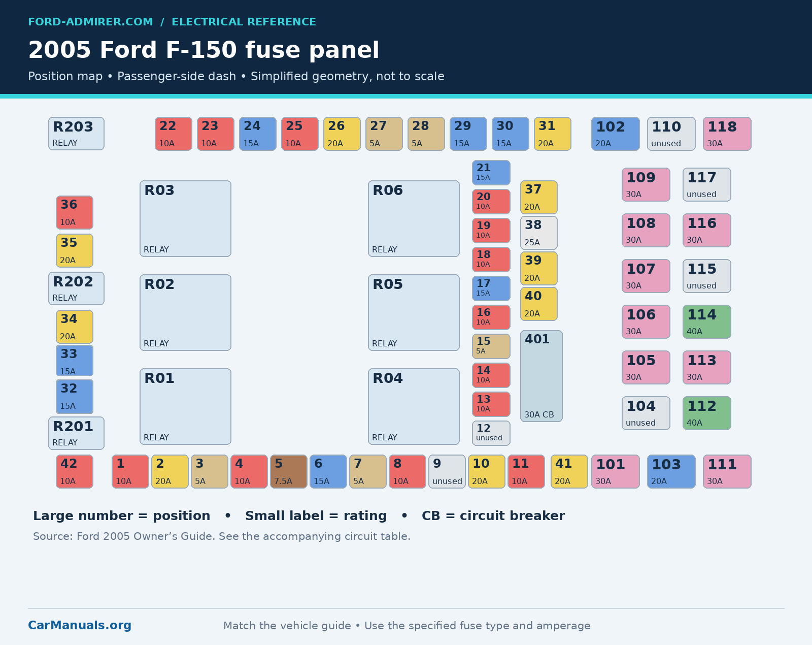
Each map shows position numbers and ratings. The colored blocks aid identification, but the printed amperage and correct fuse type are what matter. Mini and cartridge fuses use different color conventions. Position 401 is a 30A circuit breaker, not a replaceable blade fuse.
The circuit tables below contain all 61 numbered fuse and breaker entries per year. Descriptions are shortened for readability; engine and equipment qualifiers remain where relevant. Relays are listed separately after the year sections. PCM means powertrain control module; DRL means daytime running lamps; IMRC means intake manifold runner control.
2004 Ford F150 fuse box diagram
Use plain position numbers for this panel. Wiring-diagram notation such as F2.34 does not mean that Ford changed the owner-guide fuse number from 2.34 to 34. Fuse 3 is 5A, fuse 20 is 15A PCM/4×4 power, and positions 9, 12 and 30 are unused.
2004 mini fuse assignments
| Fuse | Amps | Circuits protected |
|---|---|---|
| 1 | 10 | Run/accessory: wipers, instrument cluster |
| 2 | 20 | Stop/turn lamps, speed control deactivate switch |
| 3 | 5 | Power mirrors, memory logic power, memory seats and pedals |
| 4 | 10 | DVD battery power |
| 5 | 7.5 | Keep-alive memory for PCM and climate control module |
| 6 | 15 | Park lamps, body security module, instrument panel illumination |
| 7 | 5 | Radio (start signal) |
| 8 | 10 | Heated mirrors, switch indicator |
| 9 | Not used | Not used |
| 10 | 20 | Trailer tow backup lamp relay, trailer tow park lamp relay |
| 11 | 10 | A/C clutch, 4×4 solenoid |
| 12 | Not used | Not used |
| 13 | 10 | Climate control module power |
| 14 | 10 | Backup lamp and DRL relay coil, A/C pressure switch, brake-shift interlock solenoid, heated PCV |
| 15 | 5 | Overdrive cancel, instrument cluster, brake-shift interlock |
| 16 | 10 | ABS module (run/start power) |
| 17 | 15 | Fog lamp relay |
| 18 | 10 | Run/start feed: flasher relay, auto-dimming mirror, heated seats, body security module, compass, reverse sensing |
| 19 | 10 | Restraints (airbag module) |
| 20 | 15 | PCM 4×4 power |
| 21 | 15 | Instrument cluster keep-alive power |
| 22 | 10 | Delayed accessory power: audio, door lock switch and moonroof switch illumination |
| 23 | 10 | Right low-beam headlamp |
| 24 | 15 | Battery saver power for interior lamps |
| 25 | 10 | Left low-beam headlamp |
| 26 | 20 | Horn relay, horn power |
| 27 | 5 | Passenger airbag deactivation lamp, cluster airbag lamp, cluster run/start power |
| 28 | 5 | SecuriLock (PATS) transceiver |
| 29 | 15 | PCM 4×4 power |
| 30 | Not used | Not used |
| 31 | 20 | Radio power |
| 32 | 15 | Vapor management valve, A/C clutch relay, canister vent, oxygen sensors #11/#21, charge motion control valve, MAF sensor, variable cam timing |
| 33 | 15 | Shift solenoid, downstream oxygen sensors #12/#22 |
| 34 | 20 | Fuel injectors, PCM power |
| 35 | 20 | High-beam headlamps, cluster high-beam indicator |
| 36 | 10 | Trailer tow right turn/stop lamps |
| 37 | 20 | Rear power point |
| 38 | 25 | Subwoofer power |
| 39 | 20 | Instrument panel power point |
| 40 | 20 | Low-beam headlamps, DRL |
| 41 | 20 | Cigar lighter, diagnostic (OBD) connector power |
| 42 | 10 | Trailer tow left turn/stop lamps |
2004 cartridge fuses and circuit breaker
| Fuse | Amps | Circuits protected |
|---|---|---|
| 101 | 30 | Starter solenoid |
| 102 | 20 | Ignition switch feed |
| 103 | 20 | ABS valves |
| 104 | Not used | Not used |
| 105 | 30 | Electric trailer brakes |
| 106 | 30 | Trailer tow battery charge |
| 107 | 30 | Power door locks (body security module) |
| 108 | 30 | Passenger power seat |
| 109 | 30 | Driver power seat, adjustable pedals |
| 110 | Not used | Not used |
| 111 | 30 | 4×4 relays |
| 112 | 40 | ABS pump power |
| 113 | 30 | Wipers and washer pump |
| 114 | 40 | Heated rear window, heated mirror power |
| 115 | Not used | Not used |
| 116 | 30 | Blower motor |
| 117 | Not used | Not used |
| 118 | 30 | Heated seats |
| 401 | 30 (breaker) | Power windows, moonroof, power sliding rear window |
2005 Ford F150 fuse box diagram
Fuse 20 changes function: it is now a 10A battery feed for the overhead power point. Fuse 30 becomes a second 15A PCM/4×4 feed. Fuse 3 remains 5A, and fuse 34 remains 20A for the injectors and PCM, with IMRC on the 4.2L engine.
2005 mini fuse assignments
| Fuse | Amps | Circuits protected |
|---|---|---|
| 1 | 10 | Run/accessory: wipers, instrument cluster, audio (XL/STX) |
| 2 | 20 | Stop/turn lamps, brake on/off switch |
| 3 | 5 | Power mirrors, memory seats and pedals |
| 4 | 10 | DVD battery power, power fold mirrors |
| 5 | 7.5 | Keep-alive memory for PCM and climate control module |
| 6 | 15 | Park lamps, body security module, instrument panel illumination |
| 7 | 5 | Radio (start signal) |
| 8 | 10 | Heated mirrors, switch indicator |
| 9 | Not used | Not used |
| 10 | 20 | Trailer tow backup lamp relay, trailer tow park lamp relay |
| 11 | 10 | A/C clutch, 4×4 solenoid |
| 12 | Not used | Not used |
| 13 | 10 | Climate control module power, flasher relay |
| 14 | 10 | Backup lamp and DRL relay coil, A/C pressure switch, redundant speed control switch, heated PCV (5.4L), trailer tow backup relay coil, ABS, reverse park aid, auto-dimming mirror |
| 15 | 5 | Overdrive cancel, instrument cluster |
| 16 | 10 | Brake-shift interlock solenoid |
| 17 | 15 | Fog lamp relay |
| 18 | 10 | Run/start feed: overhead power point, auto-dimming mirror, heated seats, body security module, compass, reverse sensing |
| 19 | 10 | Restraints (airbag module) |
| 20 | 10 | Battery feed for overhead power point |
| 21 | 15 | Instrument cluster keep-alive power |
| 22 | 10 | Delayed accessory power: audio, door lock switch and moonroof switch illumination |
| 23 | 10 | Right low-beam headlamp |
| 24 | 15 | Battery saver power for interior lamps |
| 25 | 10 | Left low-beam headlamp |
| 26 | 20 | Horn relay, horn power |
| 27 | 5 | Passenger airbag deactivation lamp, cluster airbag lamp, cluster run/start power |
| 28 | 5 | SecuriLock (PATS) transceiver |
| 29 | 15 | PCM 4×4 power |
| 30 | 15 | PCM 4×4 power |
| 31 | 20 | Radio power |
| 32 | 15 | Vapor management valve, A/C clutch relay, canister vent, oxygen sensors #11/#21, charge motion control valve, MAF sensor, variable cam timing, heated PCV and CID sensor (4.2L) |
| 33 | 15 | Shift solenoid, downstream oxygen sensors #12/#22, EGR (4.6L/4.2L) |
| 34 | 20 | Fuel injectors, PCM power, IMRC (4.2L) |
| 35 | 20 | High-beam headlamps, cluster high-beam indicator |
| 36 | 10 | Trailer tow right turn/stop lamps |
| 37 | 20 | Rear power point |
| 38 | 25 | Subwoofer power |
| 39 | 20 | Instrument panel power point |
| 40 | 20 | Low-beam headlamps, DRL |
| 41 | 20 | Cigar lighter, diagnostic (OBD) connector power |
| 42 | 10 | Trailer tow left turn/stop lamps |
2005 cartridge fuses and circuit breaker
| Fuse | Amps | Circuits protected |
|---|---|---|
| 101 | 30 | Starter solenoid |
| 102 | 20 | Ignition switch feed |
| 103 | 20 | ABS valves |
| 104 | Not used | Not used |
| 105 | 30 | Electric trailer brakes |
| 106 | 30 | Trailer tow battery charge |
| 107 | 30 | Power door locks (body security module) |
| 108 | 30 | Passenger power seat |
| 109 | 30 | Driver power seat, adjustable pedals |
| 110 | Not used | Not used |
| 111 | 30 | 4×4 relays |
| 112 | 40 | ABS pump power |
| 113 | 30 | Wipers and washer pump |
| 114 | 40 | Heated rear window, heated mirror power |
| 115 | Not used | Not used |
| 116 | 30 | Blower motor |
| 117 | Not used | Not used |
| 118 | 30 | Heated seats |
| 401 | 30 (breaker) | Power windows, moonroof, power sliding rear window |
2006 Ford F150 fuse box diagram
Fuse 9 is now a 20A supply for the fuel pump relay, injectors and 4.2L IMRC. Fuse 34 is a separate 15A PCM-power fuse. Fuse 12 is a 5A supply for the PCM relay coil, and fuse 3 increases to 7.5A.
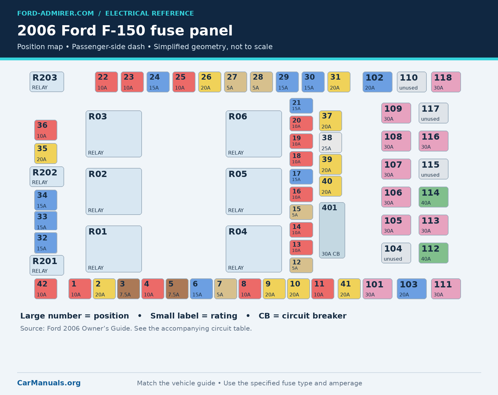
2006 mini fuse assignments
| Fuse | Amps | Circuits protected |
|---|---|---|
| 1 | 10 | Run/accessory: wipers, instrument cluster, audio (XL/STX) |
| 2 | 20 | Stop/turn lamps, brake on/off switch |
| 3 | 7.5 | Power mirrors, memory seats and pedals |
| 4 | 10 | DVD battery power, power fold mirrors |
| 5 | 7.5 | Keep-alive memory for PCM and climate control module |
| 6 | 15 | Park lamps, body security module, instrument panel illumination |
| 7 | 5 | Radio (start signal) |
| 8 | 10 | Heated mirrors, switch indicator |
| 9 | 20 | Fuel pump relay, fuel injectors, IMRC (4.2L) |
| 10 | 20 | Trailer tow backup lamp relay, trailer tow park lamp relay |
| 11 | 10 | A/C clutch, 4×4 solenoid |
| 12 | 5 | PCM relay coil |
| 13 | 10 | Climate control module power, flasher relay |
| 14 | 10 | Backup lamp and DRL relay coil, A/C pressure switch, redundant speed control switch, heated PCV (5.4L), trailer tow backup relay coil, ABS, reverse park aid, auto-dimming mirror |
| 15 | 5 | Overdrive cancel, instrument cluster |
| 16 | 10 | Brake-shift interlock solenoid |
| 17 | 15 | Fog lamp relay |
| 18 | 10 | Run/start feed: overhead power point, auto-dimming mirror, heated seats, body security module, compass, reverse sensing |
| 19 | 10 | Restraints (airbag module) |
| 20 | 10 | Battery feed for overhead power point |
| 21 | 15 | Instrument cluster keep-alive power |
| 22 | 10 | Delayed accessory power: audio, door lock switch and moonroof switch illumination |
| 23 | 10 | Right low-beam headlamp |
| 24 | 15 | Battery saver power for interior lamps |
| 25 | 10 | Left low-beam headlamp |
| 26 | 20 | Horn relay, horn power |
| 27 | 5 | Passenger airbag deactivation lamp, cluster airbag lamp, cluster run/start power |
| 28 | 5 | SecuriLock (PATS) transceiver, PCM ignition monitor |
| 29 | 15 | PCM 4×4 power |
| 30 | 15 | PCM 4×4 power |
| 31 | 20 | Radio power |
| 32 | 15 | Vapor management valve, A/C clutch relay, canister vent, oxygen sensors #11/#21, charge motion control valve, MAF sensor, variable cam timing, heated PCV and CID sensor (4.2L), EGR (4.2L/4.6L) |
| 33 | 15 | Shift solenoid, downstream oxygen sensors #12/#22, ignition coils |
| 34 | 15 | PCM power |
| 35 | 20 | High-beam headlamps, cluster high-beam indicator |
| 36 | 10 | Trailer tow right turn/stop lamps |
| 37 | 20 | Rear power point |
| 38 | 25 | Subwoofer power |
| 39 | 20 | Instrument panel power point |
| 40 | 20 | Low-beam headlamps, DRL |
| 41 | 20 | Cigar lighter, diagnostic (OBD) connector power |
| 42 | 10 | Trailer tow left turn/stop lamps |
2006 cartridge fuses and circuit breaker
| Fuse | Amps | Circuits protected |
|---|---|---|
| 101 | 30 | Starter solenoid |
| 102 | 20 | Ignition switch feed |
| 103 | 20 | ABS valves |
| 104 | Not used | Not used |
| 105 | 30 | Electric trailer brakes |
| 106 | 30 | Trailer tow battery charge |
| 107 | 30 | Power door locks (body security module) |
| 108 | 30 | Passenger power seat |
| 109 | 30 | Driver power seat, adjustable pedals |
| 110 | Not used | Not used |
| 111 | 30 | 4×4 relays |
| 112 | 40 | ABS pump power |
| 113 | 30 | Wipers and washer pump |
| 114 | 40 | Heated rear window, heated mirror power |
| 115 | Not used | Not used |
| 116 | 30 | Blower motor |
| 117 | Not used | Not used |
| 118 | 30 | Heated seats |
| 401 | 30 (breaker) | Power windows, moonroof, power sliding rear window |
2007 Ford F150 fuse box diagram
This chart follows Ford’s third-printing U.S. guide. It lists fuse 110 for the lighter/OBD supply and fuse 117 for the instrument panel power point; positions 39 and 41 are unused. Fuse 115 is a 20A spare, not the moonroof supply in this edition. See the lighter-fuse section if your truck differs.
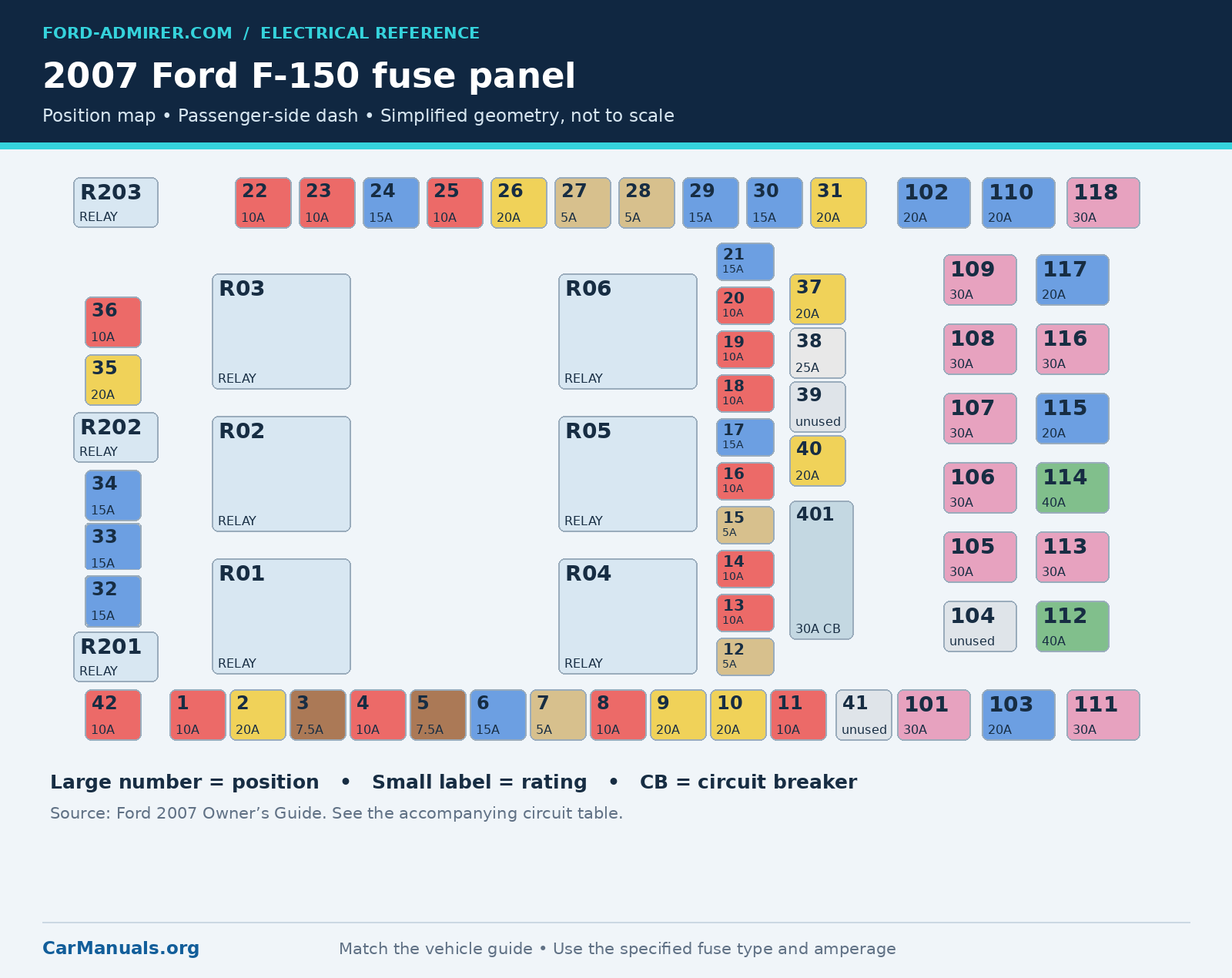
2007 mini fuse assignments
| Fuse | Amps | Circuits protected |
|---|---|---|
| 1 | 10 | Run/accessory: wipers, instrument cluster, audio (XL/STX) |
| 2 | 20 | Stop/turn lamps, brake on/off switch, hazard flashers |
| 3 | 7.5 | Power mirrors, memory seats and pedals, driver power seat |
| 4 | 10 | DVD battery power, power fold mirrors |
| 5 | 7.5 | Keep-alive memory for PCM and climate control module |
| 6 | 15 | Park lamps, body security module, instrument panel illumination |
| 7 | 5 | Radio (start signal) |
| 8 | 10 | Heated mirrors, switch indicator |
| 9 | 20 | Fuel pump relay, fuel injectors, IMRC (4.2L) |
| 10 | 20 | Trailer tow backup lamp relay, trailer tow park lamp relay |
| 11 | 10 | A/C clutch, 4×4 solenoid |
| 12 | 5 | PCM relay coil |
| 13 | 10 | Climate control module power, flasher relay |
| 14 | 10 | Backup lamp and DRL relay coil, A/C pressure switch, redundant speed control switch, heated PCV (5.4L), trailer tow backup relay coil, ABS, reverse park aid, auto-dimming mirror, navigation radio reverse input |
| 15 | 5 | Overdrive cancel, instrument cluster, traction control switch |
| 16 | 10 | Brake-shift interlock solenoid |
| 17 | 15 | Fog lamp relay |
| 18 | 10 | Run/start feed: overhead power point, auto-dimming mirror, heated seats, body security module, compass, reverse sensing |
| 19 | 10 | Restraints (airbag module), occupant classification system |
| 20 | 10 | Battery feed for overhead power point |
| 21 | 15 | Instrument cluster keep-alive power |
| 22 | 10 | Delayed accessory power: audio, door lock switch and moonroof switch illumination |
| 23 | 10 | Right low-beam headlamp |
| 24 | 15 | Battery saver power for interior lamps |
| 25 | 10 | Left low-beam headlamp |
| 26 | 20 | Horn relay, horn power |
| 27 | 5 | Passenger airbag deactivation lamp, cluster run/start power |
| 28 | 5 | SecuriLock (PATS) transceiver, PCM ignition monitor |
| 29 | 15 | PCM 4×4 power |
| 30 | 15 | PCM 4×4 power |
| 31 | 20 | Radio power, satellite radio module |
| 32 | 15 | Vapor management valve, A/C clutch relay, canister vent, oxygen sensors #11/#21, charge motion control valve, MAF sensor, variable cam timing, heated PCV and CID sensor (4.2L), EGR (4.2L/4.6L), electronic fan clutch (4.6L/5.4L) |
| 33 | 15 | Shift solenoid, downstream oxygen sensors #12/#22, ignition coils |
| 34 | 15 | PCM power |
| 35 | 20 | High-beam headlamps, cluster high-beam indicator |
| 36 | 10 | Trailer tow right turn/stop lamps |
| 37 | 20 | Rear power point, center console power point |
| 38 | 25 | Subwoofer power |
| 39 | Not used | Not used |
| 40 | 20 | Low-beam headlamps, DRL |
| 41 | Not used | Not used |
| 42 | 10 | Trailer tow left turn/stop lamps |
2007 cartridge fuses and circuit breaker
| Fuse | Amps | Circuits protected |
|---|---|---|
| 101 | 30 | Starter solenoid |
| 102 | 20 | Ignition switch feed |
| 103 | 20 | ABS valves |
| 104 | Not used | Not used |
| 105 | 30 | Electric trailer brakes |
| 106 | 30 | Trailer tow battery charge |
| 107 | 30 | Power door locks (body security module) |
| 108 | 30 | Passenger power seat |
| 109 | 30 | Driver power seat, adjustable pedals, memory module |
| 110 | 20 | Cigar lighter, diagnostic (OBD) connector power |
| 111 | 30 | 4×4 relays |
| 112 | 40 | ABS pump power |
| 113 | 30 | Wipers and washer pump |
| 114 | 40 | Heated rear window, heated mirror power |
| 115 | 20 | Spare |
| 116 | 30 | Blower motor |
| 117 | 20 | Instrument panel power point |
| 118 | 30 | Heated seats |
| 401 | 30 (breaker) | Delayed accessory power: power windows, moonroof, power sliding rear window |
2008 Ford F150 fuse box diagram
The cited 2008 guide shows a different physical arrangement, so use the map below rather than the earlier map. Fuse 115 supplies the moonroof. Fuse 34 remains 15A and adds the 4.2L IMRC listing; fuse 9 is 20A for the pump relay, injectors and injector sense.
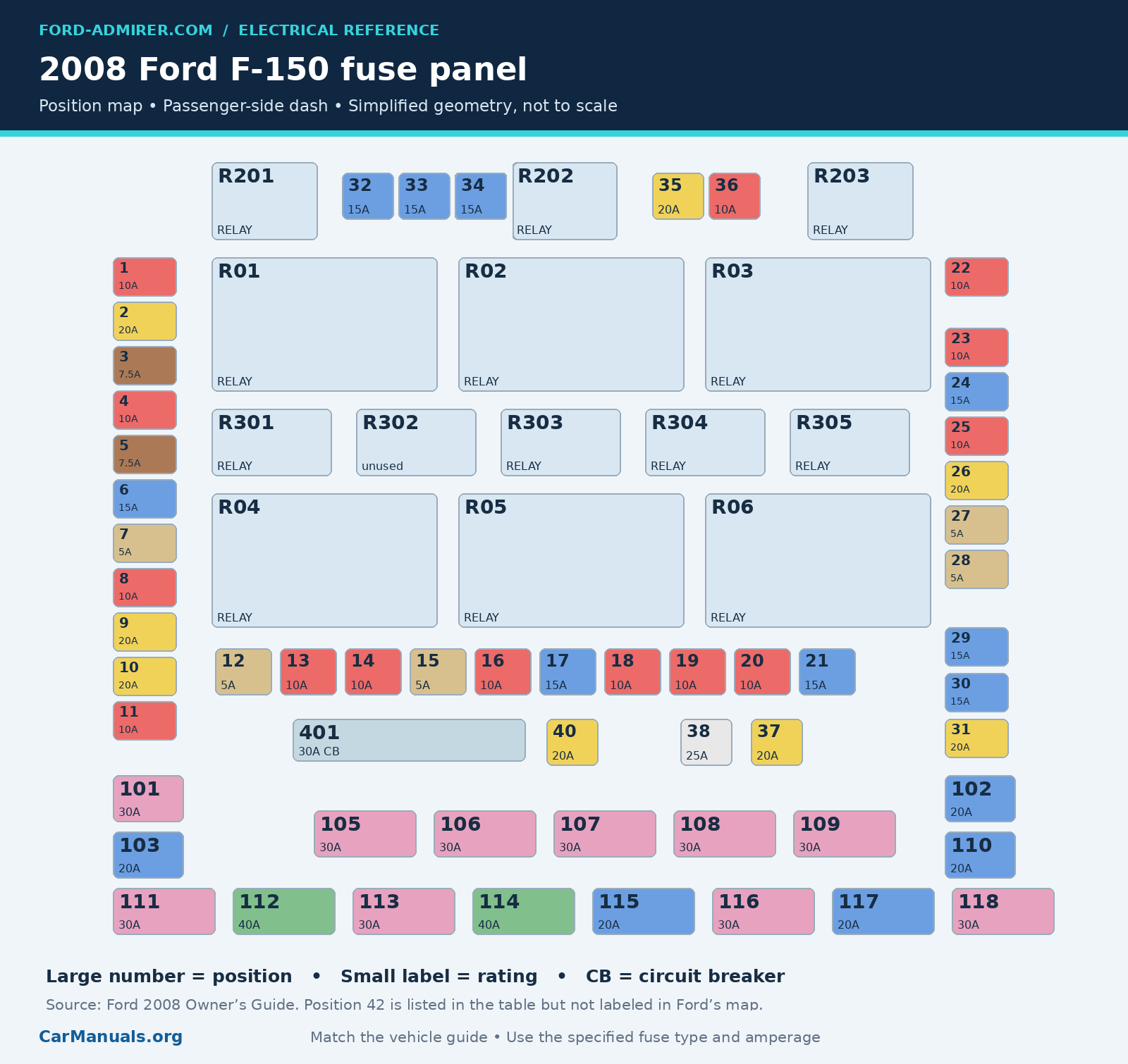
Ford’s 2008 map does not label position 42, although its table lists it as the 10A left trailer turn/stop-lamp fuse. The redrawing preserves that limitation instead of inventing a physical location. Use the truck’s matching panel information to locate it. Unused positions 39, 41 and 104 are also omitted from that map.
2008 mini fuse assignments
| Fuse | Amps | Circuits protected |
|---|---|---|
| 1 | 10 | Run/accessory: wipers, instrument cluster, audio (XL/STX) |
| 2 | 20 | Stop/turn lamps, ABS, trailer brake module, PCM brake signal, mirror turn signals, high-mount stop lamp |
| 3 | 7.5 | Power mirrors, memory seats and pedals |
| 4 | 10 | DVD battery power, power fold mirrors |
| 5 | 7.5 | Keep-alive memory for PCM and climate control module |
| 6 | 15 | Park lamps, body security module, instrument panel illumination |
| 7 | 5 | Radio (start signal) |
| 8 | 10 | Heated mirrors, switch indicator |
| 9 | 20 | Fuel pump relay, fuel injectors, injector sense |
| 10 | 20 | Trailer tow backup lamp relay, trailer tow park lamp relay |
| 11 | 10 | A/C clutch, 4×4 solenoid |
| 12 | 5 | PCM relay coil |
| 13 | 10 | Climate control module power, flasher relay |
| 14 | 10 | Backup lamp and DRL relay coil, A/C pressure switch, redundant speed control switch, heated PCV (5.4L), ABS |
| 15 | 5 | Overdrive cancel, instrument cluster |
| 16 | 10 | Brake-shift interlock solenoid |
| 17 | 15 | Fog lamp relay |
| 18 | 10 | Auto-dimming mirror, heated seats, body security module, compass, reverse sensing, power rail |
| 19 | 10 | Restraints (airbag module) |
| 20 | 10 | Power rail |
| 21 | 15 | Instrument cluster keep-alive power |
| 22 | 10 | Delayed accessory power: audio, door lock switch and moonroof switch illumination |
| 23 | 10 | Right low-beam headlamp |
| 24 | 15 | Battery saver power for interior lamps, flex fuel |
| 25 | 10 | Left low-beam headlamp |
| 26 | 20 | Horn |
| 27 | 5 | Passenger airbag deactivation lamp, cluster airbag lamp |
| 28 | 5 | SecuriLock (PATS) transceiver, PCM ignition monitor |
| 29 | 15 | PCM 4×4 power |
| 30 | 15 | PCM 4×4 power |
| 31 | 20 | Radio power, satellite radio module |
| 32 | 15 | Vapor management valve, A/C clutch relay, canister vent, oxygen sensors #11/#21, charge motion control valve, MAF sensor, variable cam timing, heated PCV and CID sensor (4.2L), EGR (4.2L/4.6L) |
| 33 | 15 | Shift solenoid, downstream oxygen sensors #12/#22, ignition coils |
| 34 | 15 | PCM power, IMRC (4.2L) |
| 35 | 20 | High-beam headlamps, cluster high-beam indicator, DRL disable relay |
| 36 | 10 | Trailer tow right turn/stop lamps |
| 37 | 20 | Rear power point |
| 38 | 25 | Subwoofer power |
| 39 | Not used | Not used |
| 40 | 20 | Low-beam headlamps, DRL |
| 41 | Not used | Not used |
| 42 | 10 | Trailer tow left turn/stop lamps |
2008 cartridge fuses and circuit breaker
| Fuse | Amps | Circuits protected |
|---|---|---|
| 101 | 30 | Starter solenoid |
| 102 | 20 | Ignition switch feed |
| 103 | 20 | ABS valves |
| 104 | Not used | Not used |
| 105 | 30 | Electric trailer brakes |
| 106 | 30 | Trailer tow battery charge |
| 107 | 30 | Power door locks (body security module) |
| 108 | 30 | Passenger power seat |
| 109 | 30 | Driver power seat, adjustable pedals, memory module (pedals and seats) |
| 110 | 20 | Cigar lighter, diagnostic (OBD) connector power |
| 111 | 30 | 4×4 motor relays |
| 112 | 40 | ABS pump power |
| 113 | 30 | Wipers and washer pump |
| 114 | 40 | Heated rear window, heated mirror power |
| 115 | 20 | Moonroof |
| 116 | 30 | Blower motor |
| 117 | 20 | Instrument panel power point |
| 118 | 30 | Heated seats |
| 401 | 30 (breaker) | Delayed accessory power: power windows, power sliding rear window |
Passenger compartment relays
The following removable relay assignments appear in all five cited guides. These are in the main panel inside the cab, not the auxiliary box under the hood. Match the relay part number and terminal arrangement before replacement.
| Relay | Type | Function |
|---|---|---|
| R01 | Full ISO | Starter solenoid |
| R02 | Full ISO | Accessory delay |
| R03 | Full ISO | High-beam headlamps |
| R04 | Full ISO | Heated rear window |
| R05 | Full ISO | Trailer tow battery charge |
| R06 | Full ISO | Blower motor |
| R201 | Half ISO | Trailer tow park lamps |
| R202 | Half ISO | Fog lamps |
| R203 | Half ISO | PCM |
Additional 2008 circuit board positions
The 2008 guide also lists these board-level positions. A printed-circuit-board relay is not a normal plug-in relay to pull and swap; use the relevant diagnostic and repair procedure.
| Relay | Type | Function |
|---|---|---|
| R301 | Printed circuit board | Trailer tow backup lamps |
| R302 | Not used | Not used |
| R303 | Printed circuit board | Fuel pump |
| R304 | Printed circuit board | Battery saver |
| R305 | Printed circuit board | Horn |
Auxiliary relay box under the hood
This box serves the A/C clutch and, where fitted, DRL and 4×4 functions. The clockspring-illumination fuse is F01 in the cited 2004 guide and F03 in the later guides. D02 for One Touch Integrated Start is already listed in the cited 2007 guide, as well as in 2008.
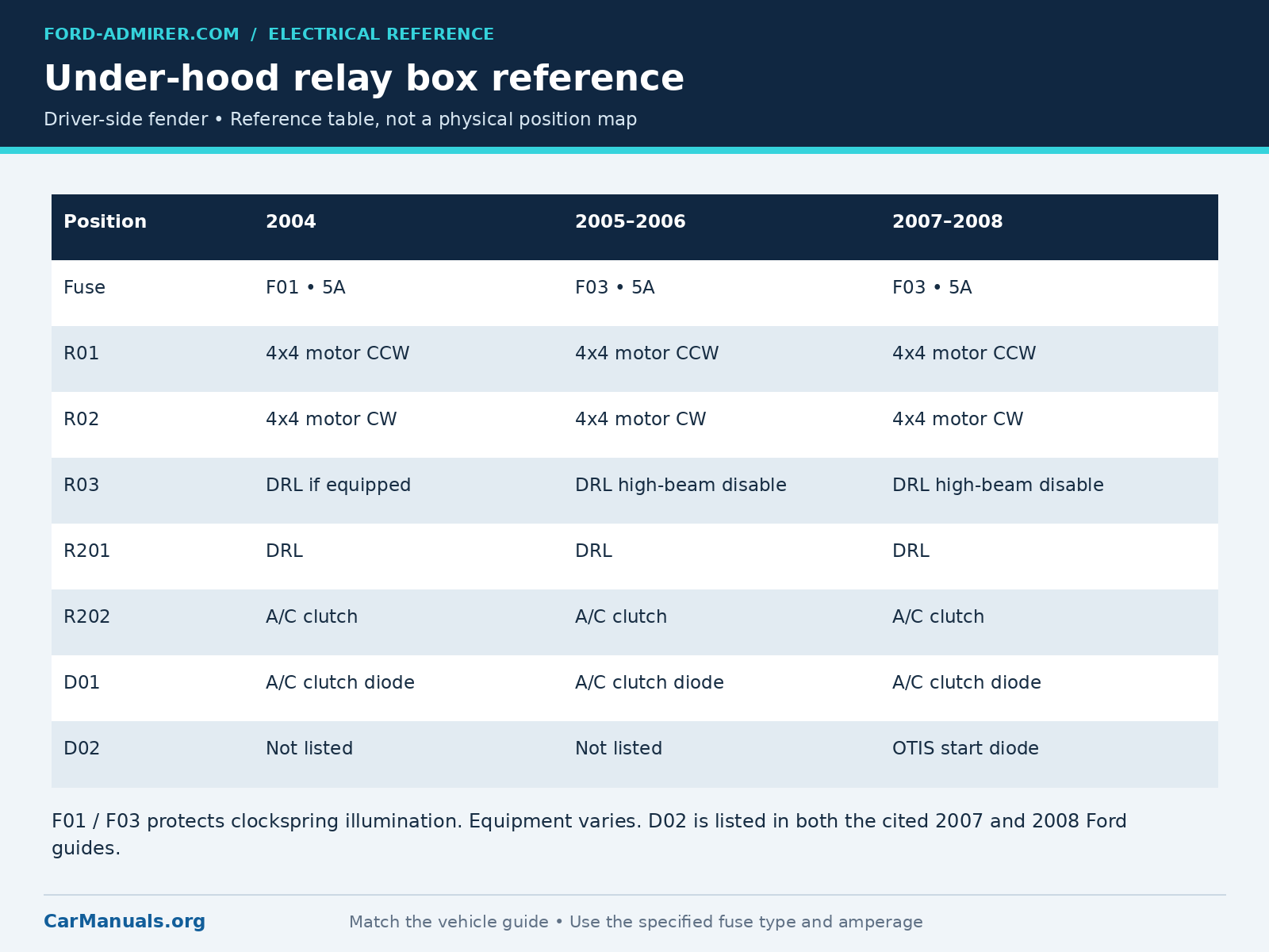
| Position | 2004 | 2005-2006 | 2007-2008 |
|---|---|---|---|
| Clockspring fuse | F01 • 5A | F03 • 5A | F03 • 5A |
| R01 | 4×4 CCW motor | 4×4 CCW motor | 4×4 CCW motor |
| R02 | 4×4 CW motor | 4×4 CW motor | 4×4 CW motor |
| R03 | DRL if fitted | DRL high-beam disable | DRL high-beam disable |
| R201 | DRL | DRL | DRL |
| R202 | A/C clutch | A/C clutch | A/C clutch |
| D01 | A/C clutch diode | A/C clutch diode | A/C clutch diode |
| D02 | Not listed | Not listed | OTIS diode |
CW means clockwise; CCW means counterclockwise. Relay and diode presence depends on the fitted equipment. The graphic is a function reference, not a physical slot map.
How to check a fuse safely
- Park securely, switch off the ignition and turn off the affected equipment. Unplug accessories from the socket or circuit being checked.
- Identify the fuse using the matching year and panel information. Ford instructs owners to disconnect the battery before servicing high-current fuses; follow the battery procedure in the owner’s guide.
- Remove the identified fuse with a suitable puller and inspect the element. A break indicates a blown fuse, but appearance alone can miss a fault. If you know how to use a meter, check continuity across the removed fuse; never use resistance or continuity mode on a live circuit.
- Install only the specified amperage and correct physical fuse type. Never use a higher rating, wire or foil in place of a fuse. Replace all covers before reconnecting the battery.
- Test the affected function. If the replacement blows, stop replacing fuses and diagnose the circuit. A fuse protects the wiring; repeated failure indicates a fault that needs attention.
Match the symptom to the circuit
Power socket or scan tool has no power: confirm which socket is affected. The lighter/OBD supply, instrument panel power point and rear power point have different feeds. Remove chargers and inspect the socket for debris or damaged contacts. A scan tool that powers up but will not communicate needs a different diagnostic path from one with no power.
Radio is dead: fuse 31 is the main 20A radio supply for every year here. The radio also has other control and accessory feeds; a good fuse 31 does not prove the whole audio circuit is sound. The satellite-radio listing appears on fuse 31 in the 2007-2008 guides.
Engine will not start: first distinguish an engine that will not crank from one that cranks but will not run. Fuse 101 protects the starter-solenoid supply. For 2006-2008, fuse 9 protects the pump-relay and injector supply; fuse 34 is a separate PCM supply. These are starting checks, not a diagnosis of a failed pump, starter or PCM.
Trailer lights fail: right turn/stop lamps use fuse 36 and left turn/stop lamps use fuse 42, both 10A. Trailer battery charge uses fuse 106, while electric brakes use fuse 105, both 30A. Check the trailer plug and wiring as well as the correct fuse; one functioning trailer circuit does not prove the others are good.
Windows stop working: check the 30A circuit breaker at position 401 and the relevant circuit information. Do not substitute a blade fuse for the breaker. Persistent or intermittent faults can also involve switches, wiring or motors.
When a wiring diagram becomes necessary
A fuse chart tells you what a position protects. It does not show every connector, splice, ground or control signal. When a fuse repeatedly fails, or the fuse is good but the component still will not operate, the next useful step is to trace the circuit for the exact year, engine and equipment.
For deeper diagnosis, browse the Ford repair information at CarManuals.org and select the F-150 manual that matches the truck. Use its wiring diagrams and test procedures alongside this reference.
Frequently asked questions
Where is the fuse box on a 2004 to 2008 F150?
The main fuse panel is below the passenger side of the dash, behind the trim and fuse cover. The auxiliary relay box is under the hood on the driver-side fender.
Which fuse powers the fuel pump on a 2006 F150?
Fuse 9 is 20A and lists the fuel pump relay, fuel injectors and IMRC for the 4.2L engine. Fuse 34 is 15A PCM power; it is not interchangeable with fuse 9.
Is the 2007 lighter fuse 41 or 110?
Ford’s third-printing 2007 U.S. guide lists fuse 110 (20A) for the lighter and diagnostic connector. Some 2007 trucks use fuse 41 instead, so check your truck’s own guide and fuse panel.
Can I use a larger fuse if the correct one blows?
No. Use the specified rating and type. A larger fuse can allow wiring to overheat before the fuse opens. Find the cause of the repeated failure.
Does this guide cover the 2004 F150 Heritage?
No. The Heritage belongs to the previous generation and requires its own fuse information.
Why do some diagrams show an F prefix?
Prefixes belong to a document’s component-labeling system. The tables here normalize the fuse positions to plain numbers; that does not mean that all years have identical circuits or physical layouts.
Sources and model coverage
The assignments were cross-checked against the following Ford U.S. owner’s-guide editions. These references define the scope of the tables; use the guide and wiring information matching the actual truck where configurations differ.
- Ford 2004 F-150 Owner’s Guide, printed pages 192-198.
- Ford 2005 F-150 Owner’s Guide, printed pages 225-230.
- Ford 2006 F-150 Owner’s Guide, printed pages 239-245.
- Ford 2007 F-150 Owner’s Guide, printed pages 276-283.
- Ford 2008 F-150 Owner’s Guide, printed pages 300-306.